
Self oscillating flyback converter
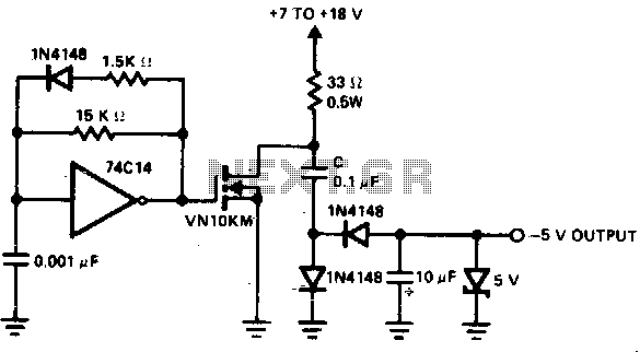
The low-power converter is engineered to efficiently step up the voltage from a primary system rail, making it suitable for use in various on-board applications, such as in electronic devices and automotive systems where space and power efficiency are critical. The converter operates at a frequency of 250 kHz, which is optimal for balancing performance and efficiency while minimizing electromagnetic interference (EMI).
The core component of this converter is a transformer, which is utilized to increase the voltage level. The transformer design should be carefully selected to handle the required power levels and ensure minimal losses during operation. The winding ratios are crucial, as they dictate the output voltage based on the input voltage. Additionally, the transformer must be rated for the operating frequency to prevent saturation and ensure efficient energy transfer.
Z1, functioning as a dissipative voltage regulator, plays a vital role in stabilizing the output voltage. It prevents voltage spikes and maintains the output within a specified range, ensuring reliable operation of downstream components. By clipping the drain voltage, Z1 protects the VMOS transistor from exceeding its breakdown voltage, which is critical for maintaining the integrity of the circuit and preventing catastrophic failures.
The overall design must also consider thermal management, as the converter may generate heat during operation. Adequate heat sinking or thermal dissipation methods should be implemented to maintain optimal operating temperatures.
In summary, this low-power converter is an essential component for applications requiring voltage step-up capabilities, with an emphasis on reliability, efficiency, and protection against voltage transients. The integration of a transformer and a voltage regulator like Z1 ensures that the converter operates within safe parameters while delivering the necessary power to the load.A low-power converter suitable for deriving a higher voltage from a main system rail in an on-board application. With the transformer shown, the operating frequency is 250 kHz Z1 serves as a dissipative voltage regulator for the output and also clips the drain voltage to a level below the rated VMOS breakdown voltage. 🔗 External reference
Related Circuits
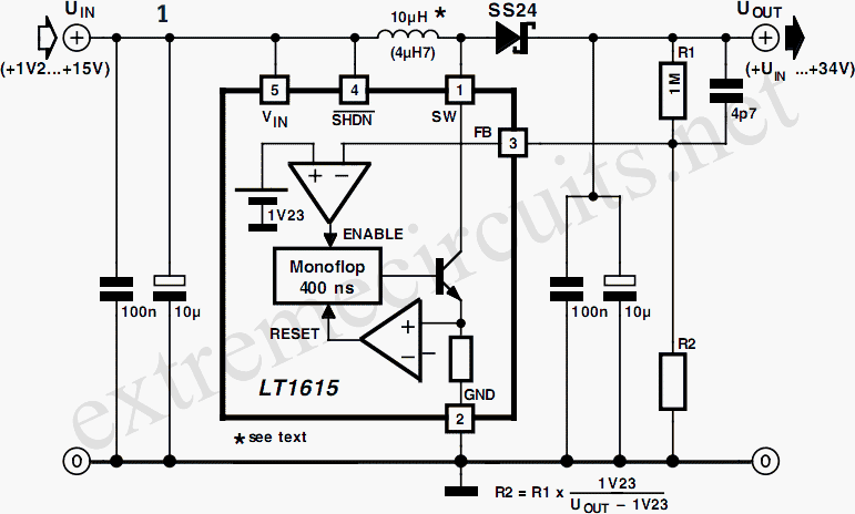
A DC/DC converter IC from Linear Technology, the LT1615 step-up switching voltage regulator, is capable of generating an output voltage of up to +34V from a supply voltage ranging from +1.2V to +15V, utilizing only a few external components....
This circuit consists of a UJT oscillator in which the timing charge capacitor C2 is linearly dependent on the input signal voltage. The charging current is set by the voltage across resistor R5, which is accurately controlled by the...
A voltage-to-frequency converter (VFC) circuit is illustrated in the schematic diagram below. The circuit utilizes a 555 integrated circuit (IC) as the central component of its operation. The voltage-to-frequency converter (VFC) is a crucial electronic circuit that converts an input...
The circuit utilizes the principle that the forward voltage of a silicon diode changes in a relatively linear manner with temperature when supplied by a constant current source. Diode D1 and resistor R2 create a potential divider connected to...
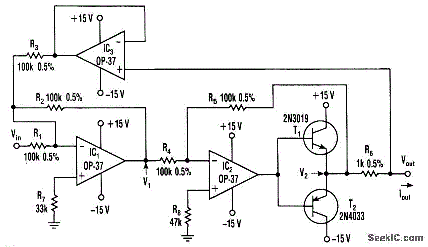
This voltage-to-current converter utilizes three operational amplifiers to control a pair of power transistors. The output current is determined by the formula: IOUT = Vin/R6. The output resistance exceeds 50 MΩ, and the output current can vary from 1...
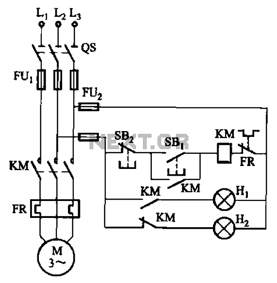
The circuit illustrated in FIG. 3 + 20 features SBi as the start button, SB2 as the stop button, Hi for run lights, and Hz for down lights. The subsequent circuit description aims to prevent tediousness by omitting the...
Warning: include(partials/cookie-banner.php): Failed to open stream: Permission denied in /var/www/html/nextgr/view-circuit.php on line 713
Warning: include(): Failed opening 'partials/cookie-banner.php' for inclusion (include_path='.:/usr/share/php') in /var/www/html/nextgr/view-circuit.php on line 713