
12V Glow Plug Converter
The described circuit efficiently converts 12 V from a standard lead-acid battery to the required 1.5 V for glow plugs, enhancing the operational efficiency of model engines. The use of a DC/DC converter, specifically the MAX 1627, allows for a compact design while maintaining high performance. The chosen FET, 2SJ349, is critical for managing the current levels, and its selection should consider both the maximum current rating and the on-resistance to minimize power losses. The fast Schottky diode, D1, is essential for preventing backflow and ensuring that the charging currents for capacitors C2 and C3 are handled effectively. The careful arrangement of components, especially the placement of C1 and C5 close to the IC, is vital for reducing parasitic inductance and resistance, which can adversely affect performance. The resistor network R2/R3 not only sets the output voltage but also plays a crucial role in feedback regulation, ensuring stable operation under varying loads. Overall, this circuit design exemplifies practical engineering solutions for powering glow plugs in model engines, highlighting the importance of component selection and layout in achieving efficient power conversion.Most small internal-combustion engines commonly used in the model-building world use glow plugs for starting. Unfortunately, glow plugs have an operating voltage of 1. 5 V, while fuel pumps, starter motors, chargers and the like generally run on 12 V. This means that a separate battery is always needed to power the glow plug. The standard solution is to use an additional 2-V lead storage battery, with a power diode in series to reduce the voltage by approximately 0. 5 V. However, this has the annoying consequence that more than 30 percent of the energy is dissipated in the diode.
Naturally, this is far from being efficient. The converter presented here allows glow plugs to be powered from the 12-V storage battery that is usually used for fuelling, charging, starting and so on. A car battery can also be used as a power source. Furthermore, this circuit is considerably more efficient than the approach of using a 2-V battery with a series power diode.
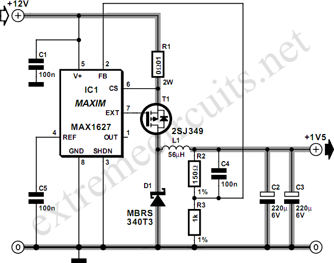
The heart of the DC/DC converter is IC1, a MAX 1627. The converter works according to the well-known step-down principle, using a coil and an electrolytic capacitor. Here the switching stage is not integrated into the IC, so we are free to select a FET according to the desired current level.
In this case, we have selected a 2SJ349 (T1), but any other type of logic-level FET with a low value of RDSon would also be satisfactory. Of course, the FET must be able to handle the required high currents. Diode D1 is a fast Schottky diode, which must be rated to handle the charging currents for C2 and C3.
This diode must also be a fairly hefty type. The internal resistances of coil L1 and capacitors C2 and C3 must be as low as possible. This ensures efficient conversion and prevents the components from becoming too warm. The resistor network R2/R3 causes 87 percent of the output voltage to be applied to the FB pin of IC1. This means that an output voltage of 1. 5 V will cause a voltage of approximately 1. 3 V to be present at the FB pin. The IC always tries to drive the switching stage such that it sees` a voltage of 1. 3 V on the FB input. If desired, a different output voltage can be provided by modifying the values of R2 and R3. When assembling the circuit, ensure that C5 and C1 are placed as close as possible to IC1, and use sufficiently heavy wiring between the 12-V input and the 1-5-V output, since large currents flow in this part of the circuit.
A glow plug can easily draw around 5 A, and the charging current flowing through the coil and into C2 and C3 is a lot higher than this! 🔗 External reference
Related Circuits
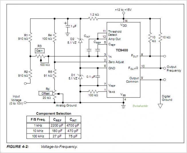
The TC9400, TC9401, and TC9402 are low-cost voltage-to-frequency (V/F) converters that utilize low-power CMOS technology. These converters accept a variable analog input signal and generate an output pulse train, with a frequency that is linearly proportional to the input...
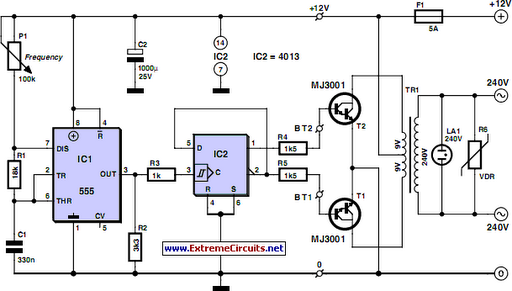
Although today's electrical appliances are increasingly self-powered, especially portable ones used for camping or summer holidays, there are still occasions when a 230 V AC source is necessary. If the power requirement from such a source remains relatively low—here,...
If you are looking for ICs for a DC to DC converter application, the LM1577/LM2577 ICs are highly recommended as they provide all the necessary power and control functions for step-up conversion. The LM1577 and LM2577 are versatile integrated circuits...
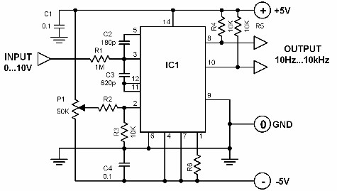
A voltage-to-frequency converter with a control range of 1:1000 can be constructed using the IC TSC9402. The specified component values in the circuit yield a conversion factor of 1 kHz per 1 V. Input voltages ranging from 10 mV...
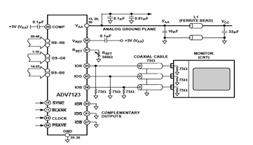
This digital-to-analog converter (DAC) integrated circuit is designed for optimal noise performance, minimizing both radiated and conducted noise. A recommended connection diagram for the ADV7123 is depicted in the following schematic diagram. According to the ADV7123 datasheet, this device...
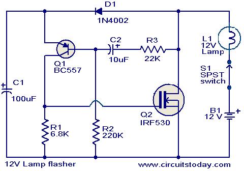
This circuit is a straightforward yet effective solution for flashing 12V lamps, particularly those utilized in automobiles. The flashing mechanism relies on transistor Q1 (BC557) and MOSFET Q2 (IRF530), with Q2 delivering the required drive for the lamp. The...