
ADV7123 Digital-to-Analog Converter Connection Diagram and Datasheet
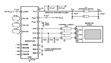
The ADV7123 is a versatile DAC offering high-speed performance and precision in converting digital signals to analog form. The three 10-bit DACs allow for the simultaneous processing of three separate channels, making it particularly suitable for applications requiring high-quality video output. Each DAC can output a voltage that corresponds to the digital input, ensuring accurate representation of the original signal.
The complementary output configuration enhances performance by providing both positive and negative voltage swings, which is crucial for applications such as video signal processing where signal integrity is paramount. The standard TTL input interface ensures compatibility with a wide range of digital systems, allowing for easy integration into existing designs.
The high impedance analog output current source is designed to drive various loads without significant signal degradation, making it ideal for interfacing with other analog components or systems. This feature is particularly beneficial in applications where signal integrity and fidelity are critical.
In terms of application, the ADV7123 is well-suited for digital video systems where it can convert digital video data into analog signals for display on monitors or televisions. Additionally, its use in image processing and digital radio modulation highlights its versatility across different fields, including telecommunications and multimedia applications. The DAC's ability to produce high-quality color graphics further expands its usability in graphics-intensive applications.
Overall, the ADV7123 DAC is a robust solution for high-speed, high-fidelity digital-to-analog conversion, making it an essential component in modern electronic systems that require precise signal processing.This digital-to-analog converter (DAC) integrated circuit is designed for lowest noise performance, both radiated and conducted noise. A recommendedconnection diagram for the ADV7123 is shown in the following schematic diagram. According tothe ADV7123 datasheet, this device consists of three high speed, 10-bit, video DACs with complementary output
s, a standard TTL input interface, and a high impedance, analog output current source. It used to be applied in digital video systems, image processing, digital radio modulation, color graphics and more. 🔗 External reference
Related Circuits
The anatomy of two ignition experiments revealed a common issue, specifically that both ends of the ignition coil are equipped with a diode. This design choice by manufacturers has implications for performance. The ignition coil generates a negative half-cycle...
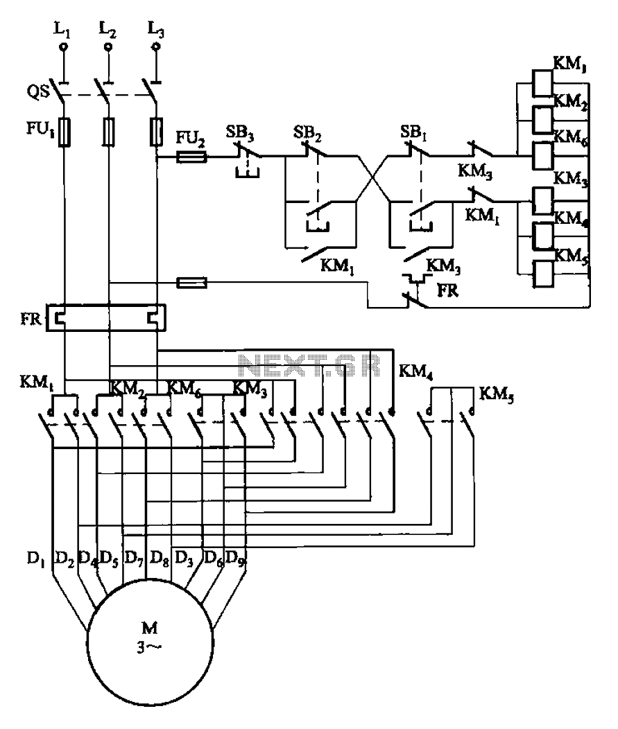
The circuit illustrated in Figure 3-107 features a low-speed operation button (SBi) and a high-speed operation button (SB2). The circuit design depicted in Figure 3-107 integrates two operational modes controlled by distinct buttons: SBi for low-speed operation and SB2 for...
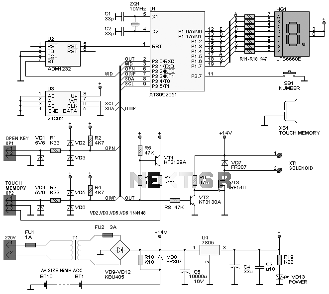
The following circuit illustrates the iButton Electronic Lock Schematic diagram. This circuit is based on the Atmel AT89C2051 integrated circuit (IC). Features include an onboard power supply comprising a transformer (T1) and a voltage regulator (U4), a bridge rectifier...
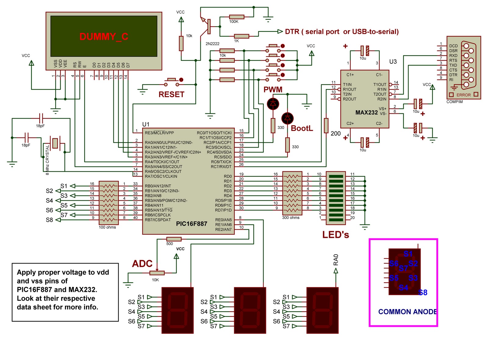
This is a demo board based on the PIC16F887 microcontroller. It serves as an excellent project for beginners working with PIC microcontrollers. The board includes a bootloader, eliminating the need for an external programmer. The circuit design is straightforward,...
This voltage-to-frequency converter is designed to connect to a frequency counter to display the measured voltage value. This converter-counter combination creates an inexpensive yet functionally complete digital voltmeter. The circuit outputs TTL-compatible pulses that are 5 µs wide. The...
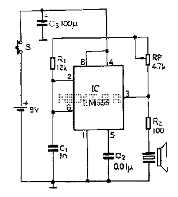
A 40 kHz ultrasonic transmitter circuit utilizes the LM555 timer as a time base circuit along with external components to create a 40 kHz multivibrator. The resistance of the adjustable resistor RP can modify the oscillation frequency. The output...
Warning: include(partials/cookie-banner.php): Failed to open stream: Permission denied in /var/www/html/nextgr/view-circuit.php on line 713
Warning: include(): Failed opening 'partials/cookie-banner.php' for inclusion (include_path='.:/usr/share/php') in /var/www/html/nextgr/view-circuit.php on line 713