
12V Halogen Dimmer
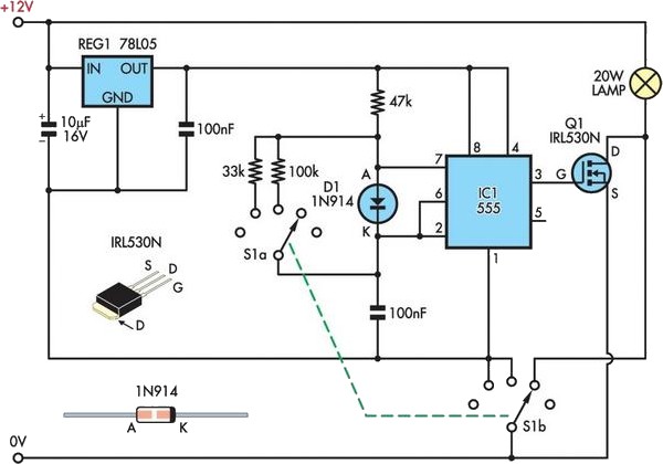
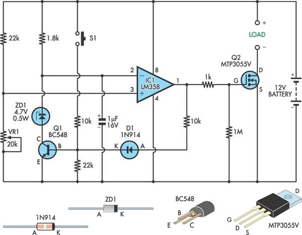
The circuit operates effectively by utilizing a 555 timer configured in astable mode to generate a PWM signal that modulates the power supplied to the halogen lamp. The rotary switch (S1) allows the user to select different duty cycles, which correspond to varying power levels. In the first two positions, the PWM signal is applied to the MOSFET, controlling the average power delivered to the lamp and thus adjusting its brightness. The third position serves as a bypass, allowing full power operation without modulation, which is useful when maximum brightness is required.
The choice of the IRL530N MOSFET is critical for maintaining efficient operation; its low on-resistance minimizes power loss during operation, enhancing the overall efficiency of the system. The absence of a heatsink simplifies the design and reduces weight, which is advantageous for a bike light application. The alternative STP30NE06L MOSFET can be used interchangeably, providing flexibility in component selection based on availability or cost considerations.
Overall, this dimmer circuit not only prolongs the battery life but also enhances the functionality of the bike light system, allowing for tailored brightness levels that suit different riding conditions.I use a 12V 20W halogen lamp (MR16) and a 4. 2Ah SLA battery for my bike light system. The battery has only limited life at this power rating, so I designed this cheap light dimmer to reduce the battery drain and allow for longer rides at night. Based on a simple 555 timer circuit and Mosfet switch Q1, it works by pulse-width modulating the 12V sup
ply to the lamp. The 555 (IC1) is wired as a free-running oscillator, with two different mark/space ratios selectable via a 2-pole, 5-position rotary switch (S1). The third switch position bypasses the electronic circuitry and connects the lamp directly to battery negative.
This gives three power levels of about 7W, 13W and 20W. A logic-level IRL530N Mosfet with a drain-source "on" resistance of only 0. 1 © ensures low losses and eliminates the need for a heatsink. An STP30NE06L Mosfet (Jaycar Cat. ZT-2271) would also be suitable. 🔗 External reference
Related Circuits
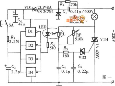
Capacitors C2 and C3, diodes VD2 and VD3, along with other components, form a simple capacitive half-wave rectifier buck power supply. The entire supply control circuit is managed by a switch (S), which can either be a standard small...
The limitation of car supply voltage (12V) forces to convert the voltages to higher in order to power audio amplifiers. This supply is intended for two channels with 50W max each (of course it depends on the amplifier used)....
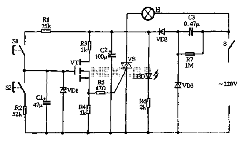
The diagram illustrates a lamp dimmer that gradually increases and decreases light intensity. This feature prevents sudden illumination, which can be a shock to the human eye, and also minimizes damage caused by inrush current when the lamp is...
The VRbot is a voice recognition module featuring multiple functions. Its dimensions are approximately 1" x 1.75". The manufacturer offers a free GUI software called VRbot GUI for setting up user-defined commands. Since the input/output data for the VRbot...
This circuit safeguards a sealed lead-acid (SLA) battery from over-discharge by disconnecting the load when the terminal voltage drops below a specified threshold. The operation involves deriving a sample of the battery voltage through a voltage divider composed of...
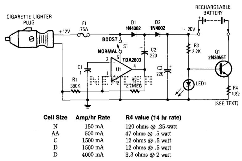
This circuit provides an output of up to 20 V from a 12-V automotive supply, enabling constant current charging of NiCad battery assemblies with a total voltage of approximately 18 V. The circuit utilizes a square-wave oscillator (VI) and...
Warning: include(partials/cookie-banner.php): Failed to open stream: Permission denied in /var/www/html/nextgr/view-circuit.php on line 713
Warning: include(): Failed opening 'partials/cookie-banner.php' for inclusion (include_path='.:/usr/share/php') in /var/www/html/nextgr/view-circuit.php on line 713