
Voice dimmer
The VRbot module's design is centered around its ability to recognize voice commands and execute corresponding actions, making it suitable for various automation projects. The integration of the VRbot with a microcontroller unit (MCU) allows for advanced functionalities, such as voice-controlled lighting systems. The use of a level shifter, such as the MAX232, is critical for ensuring compatibility between the TTL-level signals of the VRbot and the higher voltage levels typically used by PCs.
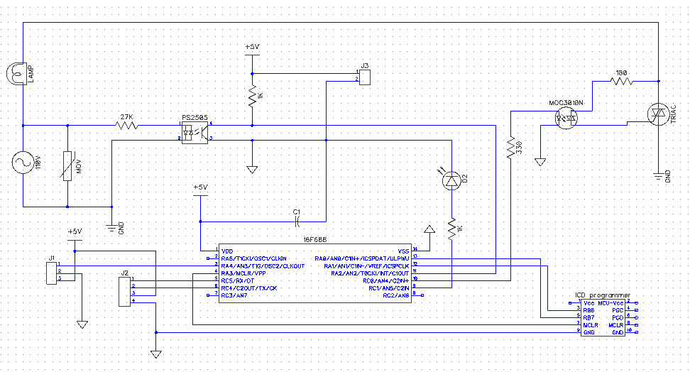
In the schematic, the PS2505 is utilized for zero-cross detection, which is essential for dimming applications to avoid flickering and to ensure smooth transitions in light levels. The MOC3010 serves as an optoisolator, providing electrical isolation between the low-voltage control side and the high-voltage load side, thereby enhancing safety in the design. The choice of the 16F688 MCU is advantageous due to its built-in UART capability, simplifying communication with the VRbot.
The software implementation includes routines for setting up the VRbot, managing its sleep state, and processing voice commands. The command structure allows for flexibility in defining various phrases and actions, enabling users to customize their experience. The communication protocol document is an invaluable resource for understanding the command structure and implementing the necessary functions in the code.
Overall, the integration of the VRbot with the MCU and the surrounding components forms a robust platform for developing voice-controlled applications, showcasing the potential of voice recognition technology in home automation and other innovative projects.I was excited when I found VRbot - a voice recognition module, that has several interesting functions such as Without hesitation, I bought one of the module for my experiment. The module size is about 1" x 1 3/4". The company provides a free download GUI software called VRbot GUI. The software is for set up User-defined commands of the module. Because input/output data coming and leaving the VRbot module are TTL level, a level shifter is need to interface with PC. MAX232 with four capacitors is excellent but any other method can be use. The picture shown below is a hook up the VRbot with the level shifter connected to a PC. Open the VRbot GUI software then click "Connent" botton. If everything works properly you should see something like a picture shown below, otherwise, you have to check the hardware connection.
The VRbot should be test with the VRbot GUI software. Okay, That was the hardware side. The next thing to do is to understand how to operate the VRbot module. All commands and description are in VRbot Communication Protocol file that you must have it as your reference. The most usefull of the document seem to be a last few page that give you comunication examples procedure.
Here are some bottom lines. The VRbot can recognize user-defined words/phases or speaker dependent (SD) from specific speaker in any language from custom wordset when recogniton command is activate. User can define words/phases or train the VRbot by using VRbot GUI software. The VRbot communicates with MCU with UART protocol with 3. 3 to 5V TTL level, normally at 9600 baud, 8 bit data, No parity, 1 bit stop, but can be change up to 115200 with a command.
Arguments that required by command shown as number in document must map into a real parameter. The argument value 0 is `A`, 1 is `B`, 2 is `C`, and so on. I was confuse passing parameter at the beginning. I built a light dimmer using IR remote in the previous project. This project I build a voice command light dimmer using VRbot. The figure shown below is a schematic. For safety purpose and more current draw in the circuit, I decide to use a transformer power supply which is not show in the schematic. PS2505 and MOC3010 are use to isolate the high voltage circuit and low voltage circuit. PS2505 is use to detect zero crossing of the main power while MOC3010 is use to drive a triac. VRbot is connect to J2 direct to MCU Rx and Tx pin. The MCU has been changed to 12F683 to 16F688 because 16F688 has a UART module. Code is devided into two parts. The first part is a perform delay using timer1 before driving a triac every zero crossing is detected.
This part is very much the same as previous dimmer project. The second part is to use VRbot recognition voice command to change dimmer level. The VRbot set up routine is use to initial the module to be ready to use. It is configed to have 5 second time out for recognition in English language. v_sleep function is to put the VRbot into sleep mode if no command is recognize within time out and will wake up with double clap. // <7465> * //*wakeup, interruptrecognitionordonothing* // <7465> * charwake_up(){ chari; for(i=0;i<9;i+){ UART1_Write(CMD_BREAK); while(!UART1_Data_Ready(); if(UART1_Read()=STS_SUCCESS)return0; delay100(); } return1; } // <7465> * //*powerdownmode, wakeupondoubleclaporreceivedcharacter* // <7465> * charv_sleep(){ UART1_Write(CMD_SLEEP); UART1_Write(ARG_ZERO+5); while(!UART1_Data_Ready(); if(UART1_Read()=STS_SUCCESS)return0; elsereturn1; } // <7465> * //*SetupVRbotbyaskID, Englishlanguage, 5secondtimeout* // <7465> * charv_setup(){ UART1_Write(CMD_ID); while(!UART1_Data_Ready(); if(UART1_Read()!=STS_ID)return1; delay150u(); UART1_Write(ARG_ACK); while(!UART1_Data_Ready(); if(UART1_Read()!=ARG_ZERO)return1; delay150u(); UART1_Write(CMD_LANGUAGE); UART1_Write(ARG_ZERO);//Englishlanguage while(!UART1_Data_Ready(); i
Related Circuits

A very simple dimmer circuit with only the essentials. In this circuit, the values are given for a BT138 at 220V AC. For 115V AC, experimentation with values may be necessary. R1 can vary from one triac to another;...
The full-wave phase control circuit described was sourced from an RCA power circuits book published in 1969. In this configuration, the load is connected in series with the AC line, while four diodes are utilized to provide a full-wave...
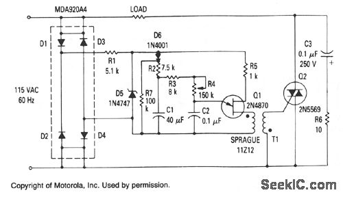
The Zener diode provides a constant voltage of 20 V to the unijunction transistor Q1, except at the end of each half-cycle of the input when the line voltage drops to zero. Initially, the voltage across capacitor C1 is...
Feedback in a public address amplifier should be avoided. The ideal solution is to adjust the positions of the microphone and speaker; however, this is not always feasible in many situations. A frequency shifter that alters the output frequency...
A useful operation for the cars is delayed extinguishing internal lighting cabin of passengers, after close some door of car. Certain cars allocate this operation from their constructor. Oldest sure do not allocate such operation. This delay makes this...
This circuit features a microphone and preamplifier that take precedence over any other audio signal, functioning similarly to a one-way intercom. When the push-to-talk switch is activated, the main amplifier switches from music playback to the voice signal. Essentially,...