
Astable multivibrator with two LED
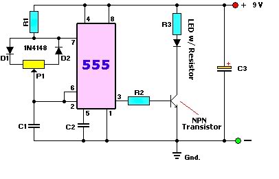
The described circuit is an astable multivibrator, a fundamental electronic configuration used for generating square wave signals. This circuit configuration employs two NPN transistors (T1 and T2, specified as BC 547B) that operate in a feedback loop, enabling them to switch on and off alternately.
The primary components involved in the operation of this multivibrator are two capacitors (C1 and C2, each rated at 22 µF), two resistors (R2 and R3, each 4.7 kOhm), and a potentiometer (P1, 100 kOhm). Resistors R1 and R4, both valued at 1 kOhm, are used to limit the base current to the transistors, ensuring they operate within their safe limits.
In this configuration, the capacitors C1 and C2 are charged through the resistors R2 and R3, which dictates the timing of the circuit. As one capacitor charges, it eventually reaches a voltage that turns on the corresponding transistor, allowing it to conduct. This action causes the other transistor to turn off, leading to a cycle where the two transistors alternate their states. The cycle time, or the frequency of the blinking LEDs (D1 and D2), is adjustable by varying the resistance of P1 or by changing the capacitance values of C1 and C2. Increasing the capacitance or resistance will slow down the blinking rate, while decreasing them will increase the blinking frequency.
The output of this circuit is visually represented by the two LEDs, which will light up alternately, providing a clear indication of the oscillation occurring within the multivibrator. This simple yet effective circuit is widely used in applications such as flashing lights, tone generators, and timers, demonstrating the fundamental principles of electronic oscillation.This is one of the basic circuitry of the electronics. The multivibrator astabiele shows two LEDs alternately light up with an adjustable speed. The circuit uses two transistors conduct alternately by the capacitors charged and discharged. The rate at which this happens depends on the capacity of capacitors of R2 and R3 and P1, and the load of the transistors. If the LEDs blink fast or too slow, P1 can be adjusted or capacitors. Greater capacity and higher resistance for blink slower. R1, R4 = 1 kOhm R2, R3 = 4.7 kOhm P1 = 100 kOhm C1, C2 = 22 V ?F/16 D1, D2 = LED T1, T2 = BC 547B 🔗 External reference
Related Circuits
A simple count-down LED timer that counts in minutes and seconds. Three buttons below the LED provide control of the unit, allowing you set the desired countdown time in minutes and seconds and a start/stop button. Completion of the...
The circuit is a comparator that can measure the voltage of a car battery in steps of 1 Volt. The voltage is determined after comparing the voltage of the battery, which is applied to the inverting inputs of amplifiers,...
A user is new to the forum and has limited experience in DIY electronics. The current project involves creating a battery-powered LED dimmer circuit. The objective of the project is to design a battery-operated LED dimmer circuit that allows for...

A 3D enhancement is required to achieve a fully three-dimensional sound experience for most stereo multimedia products. Typically, simple phase-delay circuits are utilized to create a widening effect on the perceived sound field. However, this approach can lead to...
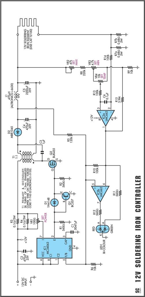
One reason commercial soldering stations are costly is that they typically use soldering irons equipped with built-in temperature sensors, like thermocouples. This circuit design eliminates the necessity for a specialized sensor by directly sensing the temperature of a soldering...

This design uses a smart card to enable a relay. A Nutchip recognizes its mating smart card among thousand similar ones, because you choose the code to be programmed in the card's memory. No specialized knowledge is necessary, as...
Warning: include(partials/cookie-banner.php): Failed to open stream: Permission denied in /var/www/html/nextgr/view-circuit.php on line 713
Warning: include(): Failed opening 'partials/cookie-banner.php' for inclusion (include_path='.:/usr/share/php') in /var/www/html/nextgr/view-circuit.php on line 713