
12V to 9 or 6 v converter
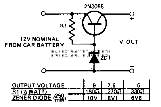
The described circuit serves as a power supply interface for various transistorized devices, utilizing the car's 12V electrical system. The circuit typically incorporates a voltage regulator to ensure stable output voltages suitable for the connected devices. This regulator can be designed using a linear voltage regulator IC or a switching regulator, depending on the efficiency requirements and the load current.
In the schematic, the input from the car's battery connects to the voltage regulator, which is responsible for providing a consistent output voltage. The table referenced in the description should enumerate the appropriate resistor values that set the current limits for the transistor, as well as the types of diodes used for rectification or protection. For example, Schottky diodes may be preferred for their low forward voltage drop, improving efficiency.
When designing for multiple voltage outputs, a switching arrangement can be implemented using relays or MOSFETs controlled by a microcontroller or manual switches. This allows the user to select the desired output voltage based on the requirements of the connected device.
For applications involving high current loads, thermal management becomes critical. The transistor should be mounted on a heatsink to dissipate excess heat generated during operation, ensuring reliable performance and preventing thermal shutdown. The heatsink must be selected based on the maximum expected power dissipation, which can be calculated using the formula P = I^2 * R, where I is the load current and R is the on-resistance of the transistor.
Overall, this circuit design is versatile and can be adapted for various applications, making it an essential component for operating transistorized devices from a vehicle's electrical system.This circuit enables transistorized items such as radio, cassettes, and other electrical devices to be operated from a car"s electrical supply. The table gives values for resistors and specified diode types fordifferent voltage. Should more than one voltage be required a switching arrangement could be incorporated For high currents, the transistor should be mounted on a heatsink. 🔗 External reference
Related Circuits
There are monitors that feature only three BNC inputs and utilize composite synchronization (sync on green). This circuit has been specifically designed for such monitors. The design maintains simplicity while delivering reasonable performance. The operational principle is straightforward. The...
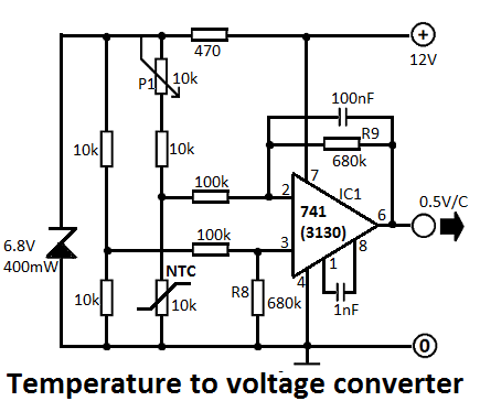
This simple temperature-to-voltage converter circuit allows for precise measurement of room temperature using an NTC resistor or thermistor. The temperature-to-voltage converter circuit typically employs a negative temperature coefficient (NTC) thermistor, which exhibits a decrease in resistance as temperature increases. This...
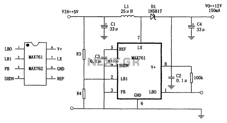
The circuit depicted in the figure illustrates an efficient, low-power step-up DC-DC converter, the MAX761, along with a few external components, which functions as a +5V to +12V boost power supply. Its characteristics include a conversion efficiency of 86%...
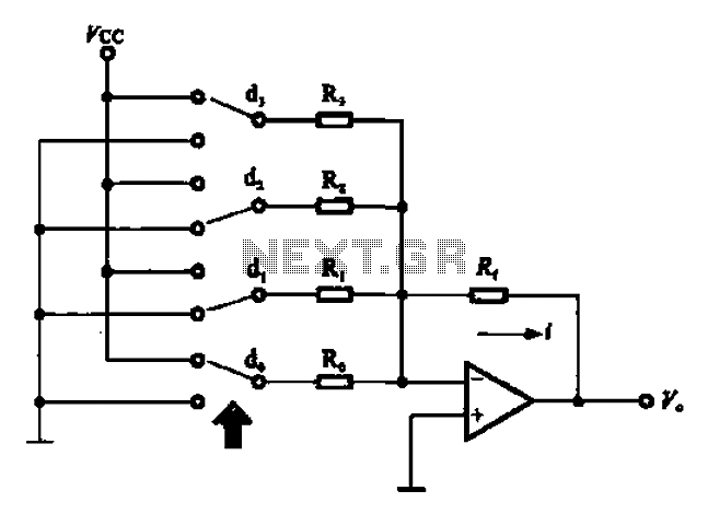
An A/D converter circuit can be represented by a simplified schematic, which illustrates a parallel type A/D converter. The term "median" refers to the number of bits in the digital signal output. The figure displays four A/D converters utilizing...
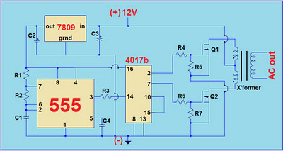
This project involves a simple 12V to 220V modified sine-wave inverter utilizing a 555 timer IC and a CD4017 decade counter. The inverter is capable of delivering 300W of continuous power and approximately 500W of maximum power output for...
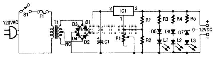
This 0- to 12-Vdc variable power supply utilizes an integrated circuit (IC) voltage regulator along with a robust transformer to deliver a dependable DC power output. The schematic illustrates that transformer T1 has a primary voltage of 120 V...