
-15 V 1-A Regulated Power Supply
The described circuit features a voltage regulation system utilizing a Darlington pair configuration with a TIP105 transistor. The circuit is designed to manage a -20 V supply voltage derived from a rectifier and filter stage, ensuring stable output voltage regulation under varying load conditions.
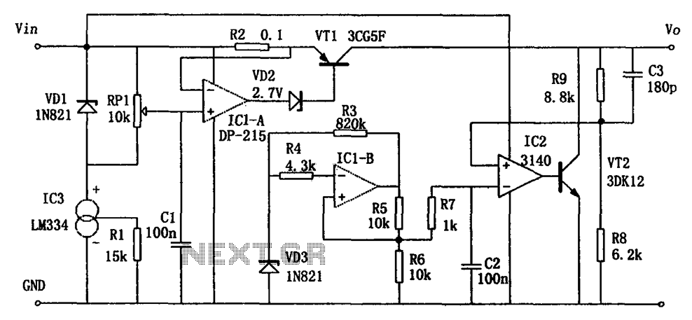
The TIP105 serves as the main pass transistor, which is a PNP type, and is responsible for controlling the output voltage. The base drive for the TIP105 is provided through resistor R5, which limits the base current and ensures proper operation of the transistor. The base voltage is influenced by a 6.2 V zener diode connected to the emitter of the uA723, a precision voltage regulator. The zener diode's anode is connected to pin 9, ensuring that the base of the TIP105 is adequately biased to maintain the desired output voltage.
The circuit also incorporates a feedback mechanism to enhance stability and response. Positive feedback is achieved through the interaction of resistors R1 and R2, which are strategically placed to sense current flow during short-circuit conditions. When the load exceeds a certain threshold, the increased current through R1 and R2 generates a voltage that forward biases the base-emitter junction of the TIP105. This action effectively increases the transistor's conduction, allowing more current to pass through and thereby stabilizing the output voltage against sudden load changes.
Overall, this circuit design is suitable for applications requiring robust voltage regulation with the ability to handle transient conditions while providing essential protection through feedback mechanisms. The careful selection of components and their configuration ensures reliable performance in various electronic applications.The supply receives -20 V from the rectifier/filter which is fed to the collector of the Darlington pnp pass transistor, a TIP105. The base drive to the TIP105 is supplied through resistor R5. The base of the TIP is driven from Vz terminal at pin 9, which is the anode of a 6.2-V zener diode that connects to the emitter of the uA723 output control transistor.
The method of providing the positive feedback required for feedback action is shown. This technique introduces positive feedback by increased current flow through resistors R1 and R2 under short-circuit conditions. This forward biases the base-emitter jun 🔗 External reference
Related Circuits
The circuit functions as a switching power supply designed to operate alongside a linear regulated power supply. Key characteristics include high efficiency and low dropout voltage. It effectively filters out high-frequency ripple voltage and manages instantaneous voltage variations, making...
This is a high-quality stabilized power supply circuit diagram. The output voltage can be adjusted from 0 volts to 30 volts DC, and the current output value can be adjusted from 0.002 A to 3 A. The circuit begins...
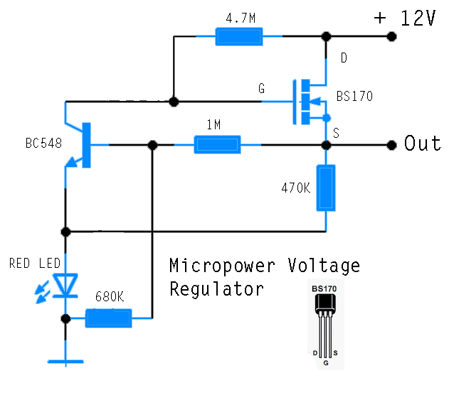
This circuit is designed to power an AVR microcontroller from a 12V lead-acid battery. The watchdog component consumes only 14 µA. While integrated circuits (ICs) from manufacturers like Linear Technology or Maxim can be utilized for this purpose, they...
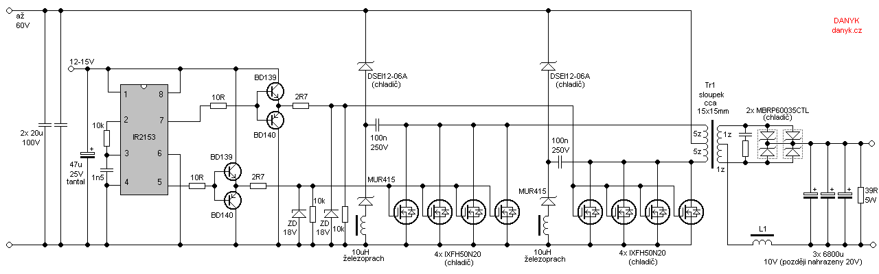
Occasionally, a low voltage power supply capable of delivering very high currents (hundreds of amperes) is required for applications such as spot welding, heating or melting metals, starting vehicle engines, or conducting various physical experiments. A decision has been...
This circuit is a modified version of a function-generator circuit. It features a battery-powered sine wave generator that can be continuously adjusted from 100 Hz to 10 kHz. The described circuit utilizes a sine wave generator to produce a continuous...
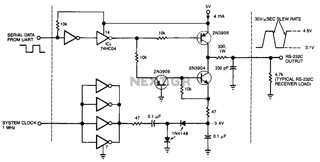
This circuit draws only 4 mA from a 5-V supply while driving a standard RS-232C receiver. The system clock drives a de-de converter that produces -3.4 V. The frequency can range from 0.5 to 8 MHz, but a range...