
Micropower Voltage Regulator Schematic Diagram
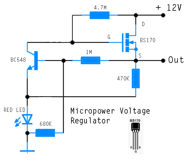
The circuit operates by utilizing a discrete design to regulate voltage for an AVR microcontroller, ensuring reliable operation from a 12V lead-acid battery. The BS170 FET serves as the primary switching element, controlled by resistor R1, which helps to manage the gate voltage and, consequently, the output voltage. The circuit’s design is straightforward, allowing for easy assembly and troubleshooting.
The output voltage regulation is achieved through the interaction between T1 and T2, where T2 acts to stabilize the output once it reaches the predetermined threshold of 5.1V. This feedback mechanism is essential for maintaining a consistent voltage supply to the microcontroller, preventing potential damage from voltage spikes.
The calculation of the output voltage takes into account the forward voltage drop across the LED (ULED) and the base-emitter voltage drop of the transistor (UBE). By incorporating the temperature coefficients of these components, the circuit can be fine-tuned for optimal performance across varying conditions.
This design is particularly advantageous in environments where sourcing specific ICs may be challenging, as it relies on widely available discrete components. Its historical context, linked to earlier designs, underscores the enduring principles of voltage regulation while adapting them to contemporary needs. Overall, this circuit exemplifies a practical approach to power regulation in microcontroller applications, with a focus on accessibility and reliability.This circuit was industrial to power an AVR microcontroller from a 12 opposed to run-acid battery. The watchdog itself draws solitary 14 µA. Of avenue, at hand are dyed-in-the-wool ICs, in lieu of model from Linear machinery or else Maxim, which can subsist used, but these can be very brutally to pick up grasp of and are commonly barely to be had during SMD letters these days. These difficulties are simply and quickly avoided using this discrete circuit. The succession control device factor is the widely-presented type BS170 FET. whilst power is useful it is driven on via R1. When the output voltage reaches 5. 1 opposed to, T2 starts to conduct and limits some advance gradient stylish the output voltage by pulling down the voltage on the gate of T1. The output voltage can be present calculated seeing that follows: Anywhere we can agreed ULED by 1. 6 in opposition to and UBE at 0. 5 V. The warmth coefficients of ULED and UBE can moreover be incorporated into the formula. The circuit is so effortless with the intention of of line someone has thinking of it ahead of. The author`s hard work control bowed up an illustration appearing in a collection of reference circuits dating from 1967: the example is very alike to this circuit, although it used germanium transistors and of choice here was refusal FET.
The voltage reference was a Zener diode, and the circuit was designed used for currents of up to 10 A. Perhaps our readers pray be there able to unearth even earlier examples of two-transistor regulators using this belief You are reading the Circuits of Micropower Voltage Regulator And this circuit permalink url it is
🔗 External reference
Related Circuits

The modification of the differential circuit is illustrated. In Figure A1, an integrator is depicted, and the output is presented. The circuit modification involves integrating the differential circuit with an integrator component, which plays a crucial role in signal processing...
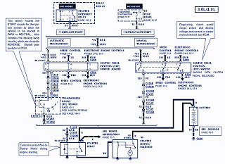
The part of the 1995 Ford Ranger wiring diagram includes components such as the transmission range sensor, electronic engine control, clutch pedal position switch jumper, speed control, automatic transmission, starter interrupt relay, relay box, starter motor during engine starting,...
The SIMD1 was enhanced in the Solar Regulator version which supplies a constant 2V after triggering and permits driving LEDs without using current limiting resistors with constant brightness. Note that you can use this Low Drop Out (LDO) linear...
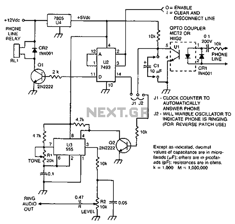
Check the loop circuit for an automatic telephone answering system or a tone generator for use in reverse automatic repair. The loop circuit in an automatic telephone answering system is designed to detect incoming calls and activate the answering mechanism....
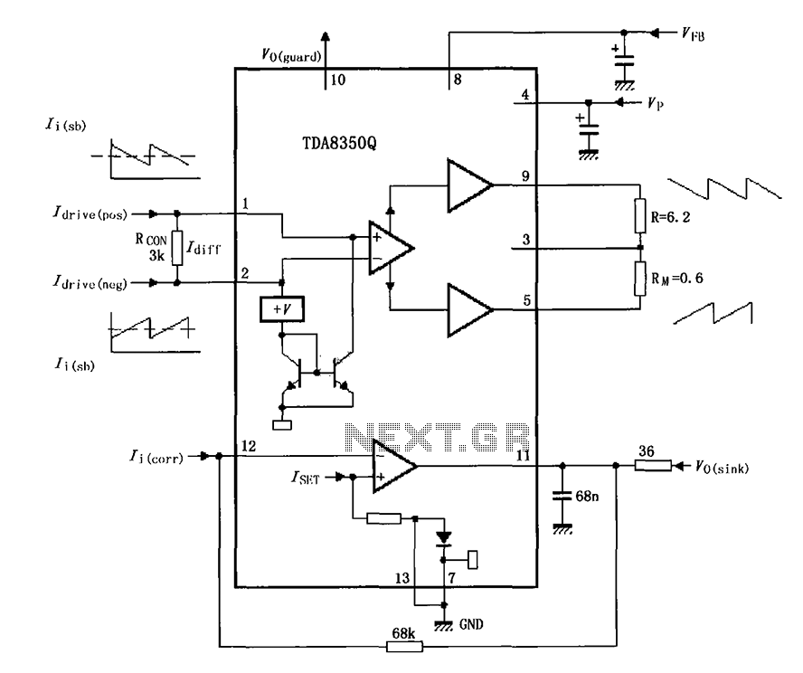
The TDA8350Q test circuit includes a push-pull amplifier configuration where the output terminal resistor serves as a dummy load for testing an alternative deflection coil. The TDA8350Q is a high-performance integrated circuit designed for use in television and display systems....
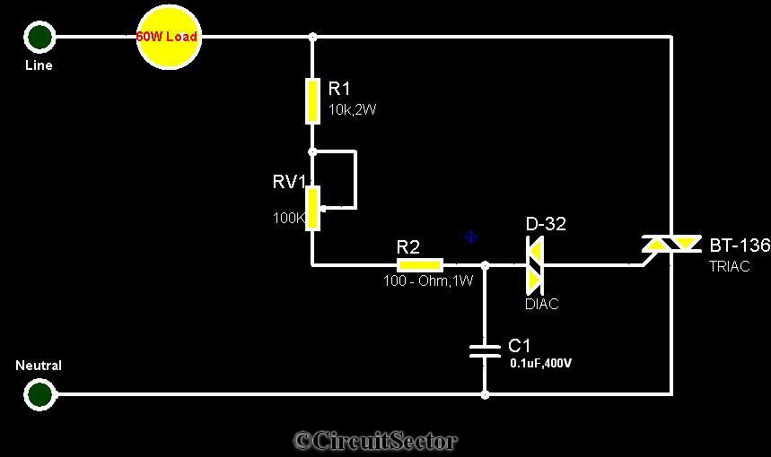
The circuit diagram presented is a triac-diac electronic fan regulator designed to reduce power consumption of electric fans, even at low speeds. Traditional resistor-inductor fan regulators tend to generate excess heat, wasting energy when the fan operates at lower...