
150W MP3 Car Amplifier
Amplifier General These devices are low-cost, high-speed, dual JFET input operational amplifiers with an internally trimmed input offset voltage (BI-FET II technology). They require low supply current yet maintain a large gain bandwidth product and fast slew rate. Additionally, well-matched high voltage JFET input devices provide very low input bias and offset currents. The LF353 is pin-compatible with the standard LM1558, allowing designers to immediately upgrade the overall performance of existing LM1558 and LM358 designs. These amplifiers may be used in applications such as high-speed integrators, fast D/A converters, sample and hold circuits, and many other circuits requiring low input offset voltage, low input bias current, high input impedance, high slew rate, and wide bandwidth. The devices also exhibit low noise and offset voltage drift.
Key specifications include:
- Internally trimmed offset voltage: 10 mV
- Low input bias current: 50 pA
- Low input noise voltage: 25 nV
- Low input noise current: 0.01 pA
- Wide gain bandwidth: 4 MHz
- High slew rate: 13 V/µs
- Low supply current: 3.6 mA
- High input impedance: 10^12 Ω
- Low total harmonic distortion: < 0.02%
- Low 1/f noise corner: 50 Hz
- Fast settling time to 0.01%: 2 µs
When the amplifier is installed in a suitcase, a switch is required to operate the system. The LA47536 has a standby function on pin 4. This pin requires a small voltage greater than 2V to activate the amplifier. Transistors Q1 and Q2 serve as a remote activation mechanism. When the driver activates the left indicator, either the back lights illuminate, or the brake is pressed, which drives Q2. This, in turn, activates Q1, applying a voltage greater than 2V to pin 4 of the LA47536.
The LA47536 is a 4-channel BTL power amplifier IC developed for car audio systems. The output stage features a pure complementary structure that utilizes V-PNP transistors on the high side and NPN transistors on the low side to deliver high power and exceptional audio quality. The LA47536 incorporates nearly all necessary functions for car audio applications, including a standby switch, a muting function, and various protection circuits. It also includes a self-diagnosis function for output offset detection.
1. Standby Switch Function (pin 4): The threshold voltage for pin 4 is set to 2 VBE. When Vst is 2.0V or higher, the amplifier is activated; when Vst is 0.7V or lower, the amplifier is deactivated. It is important to note that pin 4 requires an operating current of at least 40 µA.
2. Muting Function: The IC enters a muted state when pin 22 is grounded. In this state, the audio output is silenced. The muting function's time constant is determined by an external RC circuit, which affects the pop noise during amplifier power cycling. For recommended external component values (R=10k, C=3.3 µF), the muting on time is approximately 50 ms, while the muting off time is around 20 ms.
3. Self-Diagnosis Function (Speaker Burnout Prevention): During normal operation, the LA47536 internally monitors for abnormal amplifier output offsets and signals this condition from pin 25. Applications can prevent speaker burnout and other issues by having a system microcontroller detect this output signal and control either the standby state or the power supply. An abnormal output offset may arise from issues such as input capacitor leakage current. The signal at pin 25 is disabled by setting pin 1 to a specific state.A diagram of an active loudspeaker. The LF353 of, National Semiconductor, is going to split audio signal into three bands. SANYO LA47536 is going to amplify these signals. In stereo mode, we shall have the action of eight high speakers who are going to create a very important sound pressure. LF353 Wide Bandwidth Dual JFET Input Operational Amplifier General Description These devices are low cost, high speed, dual JFET input operational amplifiers with an internally trimmed input offset voltage (BI-FET II technology). They require low supply current yet maintain a large gain band width product and fast slew rate. In addition, well matched high voltage JFET input devices provide very low input bias and offset currents.
The LF353 is pin compatible with the standard LM1558 allowing designers to immediately upgrade e the overall performance of existing LM1558 and LM358 designs. These amplifiers may be used in applications such as high speed integrators, fast D/A converters, sample and hold circuits and many other circuits requiring low input offset voltage, low input bias current, high input impedance, high slew rate and wide bandwidth.
The devices also exhibit low noise and offset voltage drift. (National Semiconductor) Internally trimmed offset voltage: 10 mV Low input bias current: 50pA Low input noise voltage: 25 nV Low input noise current: 0. 01 pA Wide gain bandwidth: 4 MHz High slew rate: 13 V/us Low supply current: 3. 6 m High input impedance: 1012. Low total harmonic distortion : < 0. 02% Low 1/f noise corner: 50 Hz Fast settling time to 0. 01%: 2 us When the amplifier is installed behind in the suitcase, we shall need a switch works stop. The LA47536 possesses a function stand by in it pin4. This pine require a small tension superior to 2V in start up the amplifier. Transistor Q1 and Q2 makes the function of walking stop for distance. When the driver activates the left indicator, either light the back fires or press on the brake, lamps rear ignite driving Q2 who he even made to drive Q1 who applies a tension > 2V on it pin4.
LA47536 Four-Channel 45 W BTL Car Audio Power Amplifier The LA47536 is a 4-channel BTL power amplifier IC developed for use in car audio systems. The output stage features - A pure complimentary structure that uses V-PNP transistors on the high side and NPN transistors on the low side to provide high power and superb audio quality.
- The LA47536 includes almost all the functions required for car audio use, including a standby switch, a muting function, and each protection circuit. It also provides a self-diagnosis function (output offset detection). (Sanyo) 1. Standby Switch Function (pin 4) The pin 4 threshold voltage is set to be 2 VBE. When Vst is 2. 0V or higher, the amplifier will be on, and when Vst, is 0. 7V or lower, the amplifier will be off. Note that pin 4 requires an operating current of at least 40uA. 2. Muting Function The IC is set to the muted state by setting pin 22 to the ground potential. In this state, the audio output is muted. The time constant with which the muting function operates is set by an external RC circuit, and this time constant influences the pop noise that occurs when the amplifier is turned on or off.
The muting on and off times due to the recommended external component values (R=10k, C=3. 3uF) are as follows. Muting on time: 50ms Muting off time: 20ms 3. Self-Diagnosis Function (Speaker burnout prevention) During steady state operation, the LA47536 detects, internally, whether or not an abnormal amplifier output offset has occurred, and outputs this signal from pin 25. Applications can prevent speaker burnout and other problems by having the system microcontroller detect this pin 25 output signal and control either the standby state or the power supply.
(An abnormal output offset may be caused by, for example, input capacitor leakage current. ) The pin 25 signal is turned off by setting pin 1 t 🔗 External reference
Related Circuits
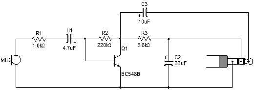
Most sound card microphone inputs require a minimum signal level of at least 10 millivolts, but some older 8-bit cards need as much as 100 millivolts. The typical impedance of the PC sound card microphone input is in the...
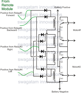
The market is filled with high-end remote-controlled toy cars; however, for hobbyists, creating one at home can be a unique experience. The following article explains how to configure a simple remote-controlled toy car using a pre-made 4-relay remote control...
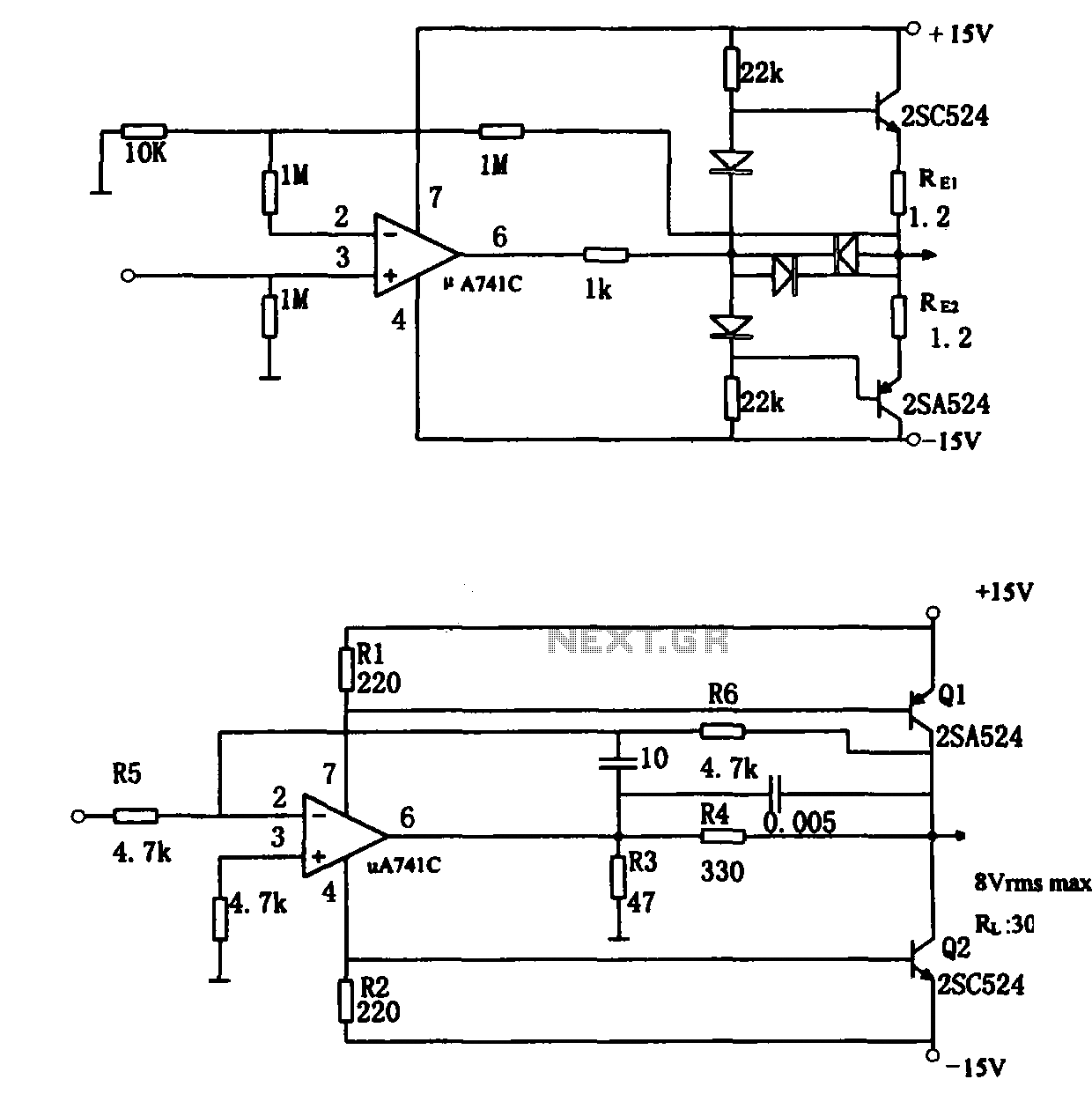
The direct coupling audio power amplifier utilizes an integrated operational amplifier. There are typically two practical configurations. The first configuration, depicted in (a), features a circuit structure that includes the output of the operational amplifier and a complementary symmetry...
The Park Aid system utilizes three LEDs to indicate the distance of a bumper barrier through infrared operation, designed for indoor use. The circuit diagram includes the following components: R1 (10K 1/4W resistor), R2, R5, R6, R9 (1K 1/4W...
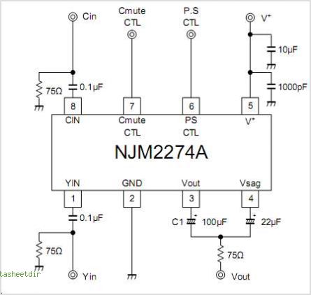
The NJM2574 is a low voltage video amplifier that includes a low-pass filter (LPF) circuit, a driver, and an internal clamp/bias function. It is designed to connect directly to a TV monitor using a composite input signal of 0.5V...
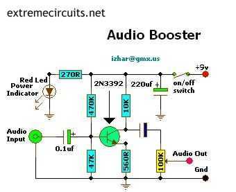
This small amplifier circuit is ideal for boosting small audio units. The small amplifier circuit is designed to enhance the audio signals from low-output devices, such as microphones or portable music players. It typically employs a transistor or an operational...