
Up/Down Timer For A Power Antenna
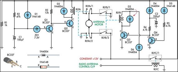
The circuit operates as follows: when the radio antenna control output is off (i.e., the radio is off), relay RLYC remains off, which in turn keeps relay RLYA and the motor off. Conversely, when the radio is turned on, the radio antenna control output line switches to +12V. This action causes RLYC to close its contacts and power the circuit. Consequently, capacitor C2 (330µF) charges rapidly through diode D4, while transistor Q4 is biased on via diode D5 and resistor R5, ensuring that Q3 and relay RLYB remain off. Simultaneously, Q2 is activated, powering relay RLYA and driving the motor to extend the antenna. During this process, capacitor C1 charges through resistor R2. Once the voltage across C1 reaches +8.1V, transistor Q1 is activated via ZD1, turning off Q2 and consequently deactivating the relay, which initiates the "up" timeout. The specified values for C1, R2, and ZD1 yield an "up" duration of approximately 6 seconds, sufficient to fully extend the antenna. Diode D1 discharges capacitor C1 through resistor R1 when the +12V supply is removed.
When the radio is switched off (or a CD is inserted into the stereo unit), the radio antenna control output returns to 0V. This action results in Q4 turning off, allowing Q3 to turn on due to the stored charge in C2. Q3 and relay RLYB activate for about six seconds, during which C2 discharges through resistor R4, reversing power to the motor and retracting the antenna. Diodes D4 and D5 are included to prevent C2 from discharging back through the circuitry connected to Q1 and Q2.
This circuit design effectively addresses the need for a reliable power antenna control system in vehicles where the original body computer integration is bypassed due to aftermarket audio system installations. The timed control mechanism ensures proper operation without the need for limit switches, providing a functional and efficient solution for antenna management. The use of capacitors, resistors, and transistors allows for precise control over the antenna's movement, ensuring that the system operates seamlessly in conjunction with the vehicle's audio system.This up/down timer was designed to control a power antenna on a late-model vehicle. Normally, this vehicle uses a body computer to control the antenna. However, the person who owned the vehicle wanted to install his own high-powered audio stereo system. The original stereo system was tied in with the body computer and this meant that a separate an tenna controller was required for the after-market sound system. Also, the power antenna fitted did not have limit switches inside, hence the need for a timed control circuit. Here`s how the circuit works. first, assume that the radio antenna control output is not switched on - ie, the radio is switched off.
In that case, relay RLYC will be off and so relay RLYA will also be off, as is the motor. Conversely, when the radio is switched on, the radio antenna control output line switches to +12V. And when that happens, RLYC closes its contacts and applies power to the circuit. As a result, C2 (330OF) quickly charges via D4, while Q4 is biased on via D5 and R5. This ensures that Q3 and relay RLYB remain off. At the same time, Q2 is is turned on, thus turning on RLYA and applying power to the motor. This drives the antenna in the up direction. During this time, C1 charges via R2. When the voltage across the capacitor reaches +8. 1V, Q1 turns on via ZD1 and so Q2 turns off and switches off the relay - ie, this gives the "up" timeout. Using the values shown for C1, R2 and ZD1 gives an "up" duration of approximately 6 seconds - long enough to fully extend the antenna.
D1 discharges C1 (via resistor R1) when the +12V supply is later removed. When the radio is switched off (or a CD placed into the stereo unit), the radio antenna control output switches back to 0V. This does several things: first, it turns Q4 off and this allows Q3 to turn on due to the stored charge in C2.
Q3 and RLYB now turn on for about six seconds - ie, while C2 discharges via R4 - and this switches power to the motor in the opposite direction to drive the antenna down. Diodes D4 and D5 are there to prevent C2 from discharging back via the circuitry around on Q1 and Q2.
🔗 External reference
Related Circuits
A few years ago, a diode-sensor based RF power meter was built using a 68HC11 microprocessor. Prior to that, an analog RF power meter with a thermal power sensor was developed. The datasheets for logarithmic amplifiers, which promised a...
The Adjustable Timer circuit initiates timing upon activation. A green LED illuminates to indicate that timing is in progress. Once the designated time period elapses, the green LED turns off, the red LED activates, and an audible bleeper sounds....
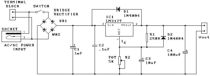
A potentiometer, designated as R2, can be utilized to adjust the desired output voltage. The kit is capable of accepting either AC or DC input through a socket or terminal block. It is advisable to incorporate protection diodes when...
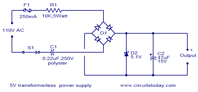
The circuit diagram illustrates a 5V transformerless power supply utilizing minimal components. The operation of this circuit is straightforward. Resistor R1 serves as a current limiter, while bridge D1 rectifies the mains voltage. The Zener diode regulates the output...
This is a power audio amplifier circuit based on the STK400xx series. It provides high-quality sound and is cost-effective, as the STK40xx series is affordably priced. The circuit can be easily constructed using only a few external components. The...
A switched timer for intervals of 5 to 30 minutes incremented in 5 minute steps. Simple to build, simple to make, nothing too complicated here. However, you must use the CMOS type 555 timer designated the 7555; a normal...
Warning: include(partials/cookie-banner.php): Failed to open stream: Permission denied in /var/www/html/nextgr/view-circuit.php on line 713
Warning: include(): Failed opening 'partials/cookie-banner.php' for inclusion (include_path='.:/usr/share/php') in /var/www/html/nextgr/view-circuit.php on line 713