
16w 12v fluorescent inverter with AC output
The inverter functions by converting direct current (DC) into alternating current (AC) to power fluorescent lamps. The preheating process is crucial, as it enhances the efficiency of the lamp's electrodes, allowing for a quicker start and reducing flicker. The inverter typically incorporates a high-frequency oscillator circuit, which generates the necessary AC voltage to ignite the gas within the fluorescent tube.
Key components of the inverter include a transformer, which steps up the voltage to the required level, and a series of capacitors and inductors that help filter and stabilize the output. The circuit is designed to provide a consistent and reliable power supply, ensuring that the fluorescent lamp operates at its rated efficiency.
Additionally, safety features are often integrated into the design, such as overcurrent protection and thermal shutdown mechanisms, to prevent damage to both the inverter and the lamp. This inverter is suitable for various applications, including residential and commercial lighting solutions, where energy efficiency and longevity of the light source are of paramount importance.
Overall, this inverter represents an effective solution for driving fluorescent lamps, ensuring optimal performance through its preheating capability and robust electrical design.This inverter will drive any fluorescent lamp between 8w and 20w but works best with 16w tubes. It preheats the electrodes and keeps them heated while.. 🔗 External reference
Related Circuits
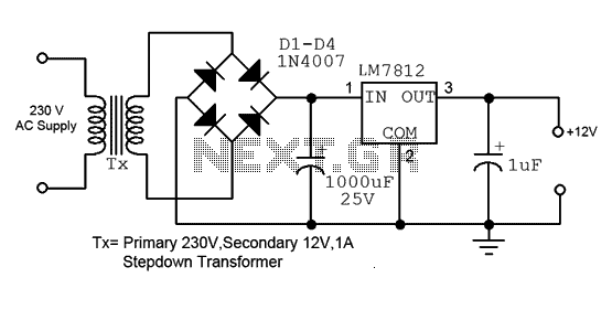
This is a straightforward 12V power supply circuit diagram. It features a fixed voltage output and is based on the LM7812 voltage regulator integrated circuit. The 12V power supply circuit utilizing the LM7812 voltage regulator is designed to provide a...
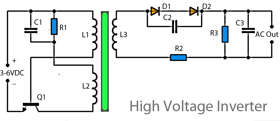
This inverter circuit operates using a transistor and transformer, along with other components, to elevate the voltage. The input supply voltage ranges from 3V to 6V DC, which is then converted to a high voltage AC output. However, the...
This circuit provides a short circuit protected power supply from PC 12V supply voltage. This is particularly handy when working with PC interfacing projects. More: Fig-1 shows the circuit diagram of the complete power supply. The necessary 12V supply...
Many circuits can be powered directly from the mains with the aid of a series capacitor (C1). The disadvantage of this approach is that usually only one half cycle of the mains waveform can be used to produce a...
This article presents an overview of fluorescent dimming and an application circuit for low-end small fixture applications ICs, where dimming levels below 10% are required alongside comprehensive protection features. The electronic ballast circuit block diagram includes the AC line...
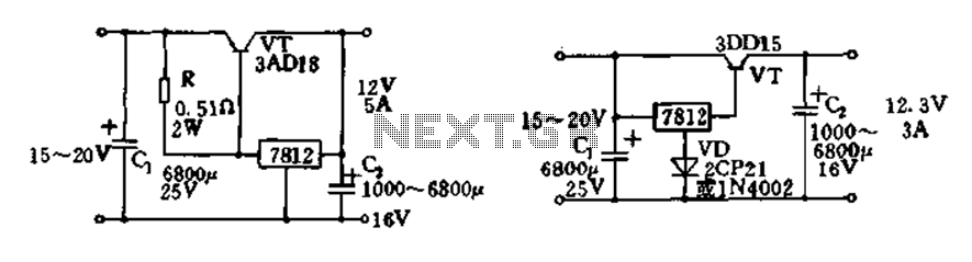
Expand integrated three-terminal regulator block circuit output current method The integrated three-terminal regulator is a versatile component commonly used in power supply circuits to provide a stable output voltage. This regulator typically consists of three terminals: input, output, and ground....