
PC 12V ADAPTER
This circuit is designed to draw a regulated 12V power supply from a standard PC power supply unit (PSU), which typically outputs various voltages including 12V, 5V, and 3.3V. The primary function of this circuit is to safeguard the PC power supply from potential short circuits that can occur during interfacing projects.
The circuit typically includes a fuse or a resettable polyfuse to provide short circuit protection. This component is placed in series with the output of the 12V line from the PSU, ensuring that if a short circuit occurs, the fuse will blow or reset, thus disconnecting the load and protecting the power supply.
In addition to the fuse, a voltage regulator may be incorporated to ensure a stable output voltage. Common voltage regulators for 12V applications include the LM7812, which can provide a regulated output while handling input voltage variations. Capacitors are also used in conjunction with the voltage regulator to filter out noise and stabilize the output voltage.
The circuit may also include indicator LEDs to show the status of the power supply, providing visual feedback that the circuit is operational. Furthermore, appropriate heat sinking may be necessary for the voltage regulator to dissipate heat generated during operation, ensuring reliable performance.
Overall, this circuit is essential for projects that require a stable and protected power source derived from a PC power supply, making it a valuable addition for hobbyists and engineers working on interfacing applications.This circuit provides a short circuit protected power supply from PC 12V supply voltage. This is particularly handy when working with PC interfacing projects. Fig-1 shows the circuit diagram of the complete power supply. The necessary 12V supply voltage is taken directly from the PC power supply. In order to protect the PC supply against possible short circuits, and especially to prevent the the PC from being c 🔗 External reference
Related Circuits
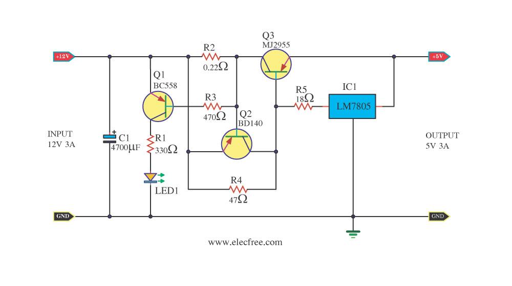
Today, a 12V to 5V 3A DC converter step-down regulator circuit has been presented. Sometimes, individuals have a 12V 3A power supply but require a 5V 3A output for digital circuits. This circuit fulfills that requirement by utilizing standard...
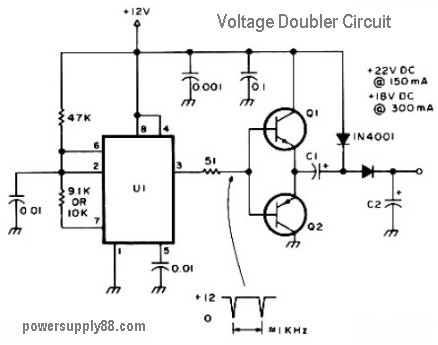
The schematic diagram originates from a 12V DC voltage doubler circuit power supply. This circuit diagram illustrates a DC voltage doubler/DC converter that transforms a 12V DC power supply into 24V DC and 18V DC outputs. It is compatible...
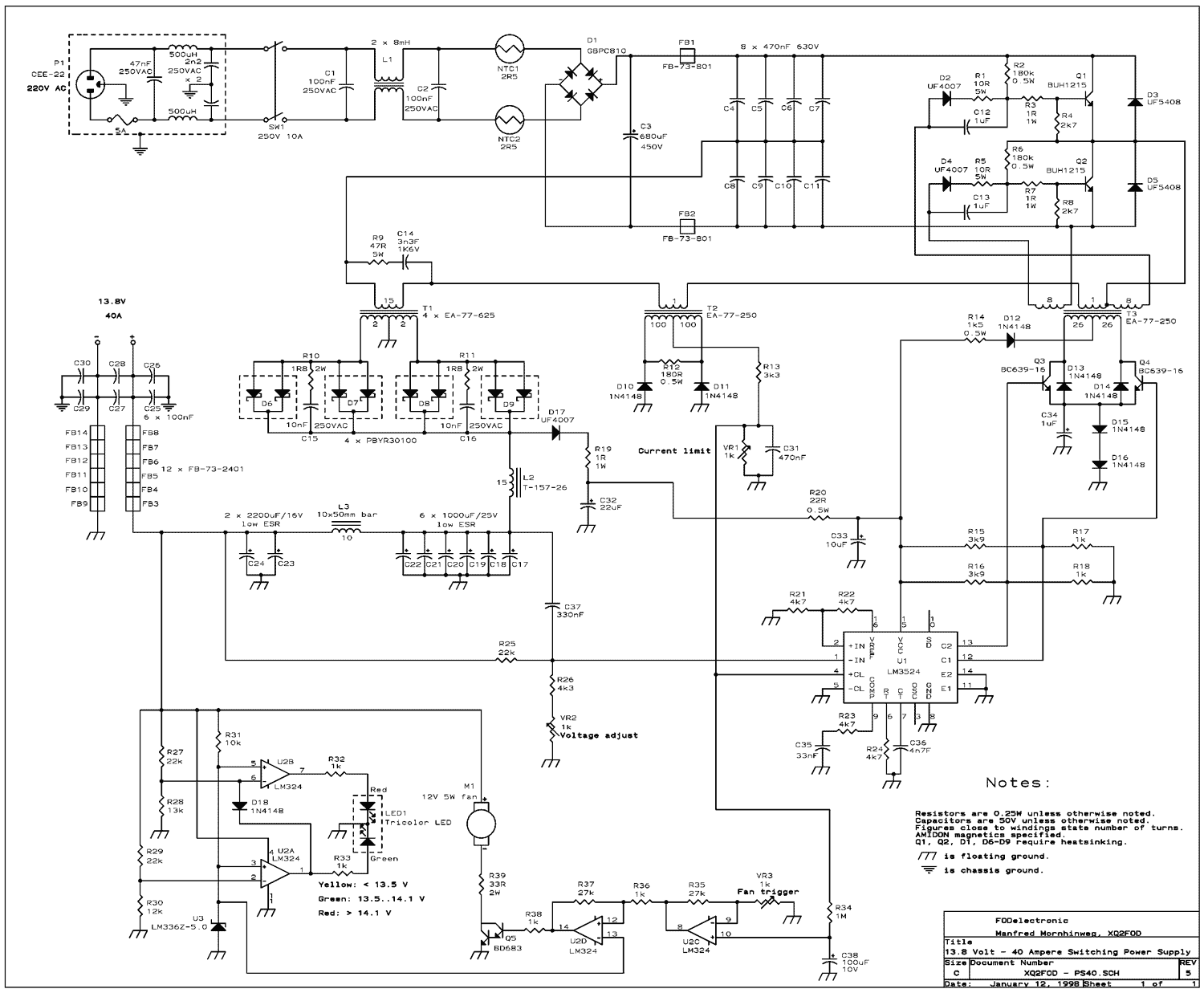
The present trend is to use ever higher frequencies. But by doing so it becomes more difficult to filter out the RF noise inevitably generated by the switching. So I decided to stay at a low switching frequency of...
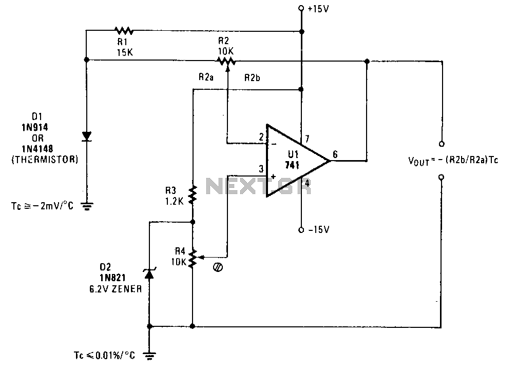
A simple operational amplifier and silicon diode form the core of a temperature-to-voltage converter, which allows the use of a standard voltmeter—either analog or digital—to measure temperature. User adjustments enable readings of either 10 mV or 100 mV to...
A 12V to 3V converter. This is a simple and inexpensive circuit designed to convert voltage from 12V to 3V. In fact, this is a basic regulator circuit. This 12V to 3V converter circuit typically employs a linear voltage regulator,...
The following circuit diagram represents a battery charger designed for a 12V car battery. This circuit includes overcharging protection, which automatically disconnects the charging circuit. Unlike typical battery chargers that continuously supply a few amperes to the battery while...