
18 LED sequencer timer
Note that the 4017 counter will not deliver much current, and so the LED current is set to about 6mA using a 1.5K resistor in series. For more current, you could use transistors on each output as shown in the drawing above, (10 Channel LED Sequencer). But some of the newer bright LEDs are fairly bright at 6mA.
The circuit utilizes two CD4017 decade counters, which are designed for counting applications. Each CD4017 can count from 0 to 9, and by cascading two of them, the total count can be extended to 18. The reset function is implemented using a 15K ohm resistor and a 10µF capacitor connected to pin 15 of the first counter. This configuration ensures that when power is applied, the counters reset to zero, with pin 3 outputting +12V while all other outputs remain low.
The clock pulse is managed through an AND gate formed by two 1N914 diodes and a 15-ohm resistor. This configuration allows the clock pulses to be directed to the second counter only when the first counter is in the appropriate state. Specifically, when the first counter reaches its maximum count (9), pin 11 goes high, allowing the clock pulse to flow to the second counter. This mechanism prevents the second counter from advancing until the first counter has completed its cycle.
The cascading effect is achieved by controlling the clock pulses with the state of pin 3 from the first counter. While the first counter is counting, pin 3 remains low, blocking any clock pulses from advancing the second counter. Once the first counter resets, pin 3 goes high, allowing the cycle to repeat.
The output from each counter is connected to LEDs, with a current-limiting resistor of 1.5K ohms set to allow approximately 6mA through each LED. This current level is sufficient for standard LEDs, while newer high-brightness LEDs may still provide adequate illumination at this current. If higher current is desired, the circuit can be modified to include transistors at each output, enhancing the output driving capability without exceeding the current limits of the CD4017 counters.
This cascading LED sequencer design is effective for creating visual counting displays and can be adapted for various applications requiring sequential light activation.The question sometimes comes up of how to cascade 4017 decade counters for more than 10 sequencial stages. The LED sequencer below shows a possible solution using a few extra parts. When power is applied, the 15K resistor and 10uF cap at pin 15 will reset the counters to the zero count where pin 3 is at +12 and all other outputs are at zero.
The 2 diodes (1n914) and 15 resistor form a AND gate so the clock pulse will be passed to the right side counter when the sequence starts. When the right counter reaches the 10th count, pin 11 will move high enabling the AND gate on the right to pass the clock pulse to the left side counter.
As the left side counter advances, pin 3 will be low so that clock pulses cannot advance the right counter. When the left counter turns over and pin 3 again moves high, the sequence will repeat. Thus we get 18 total counts, 9 from the first counter, and 9 from the second. Note that the 4017 counter will not deliver much current, and so the LED current is set to about 6mA using a 1.5K resistor in series.
For more current, you could use transistors on each output as shown in the drawing above, (10 Channel LED Sequencer). But some of the newer bright LEDs are fairly bright at 6mA. 🔗 External reference
Related Circuits
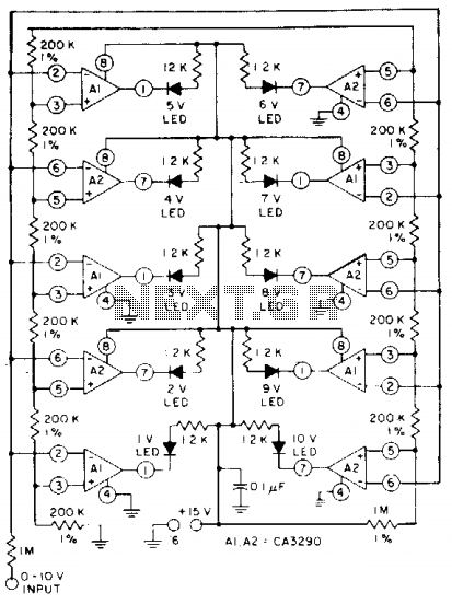
The circuit utilizes CA3290 BiMOS dual voltage comparators. The non-inverting inputs of A1 and A2 are connected to a voltage divider reference. The input signal is applied to the inverting inputs. LEDs are activated when the input voltage reaches...
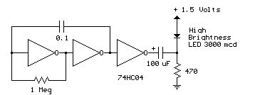
Several 1.5 V LED flasher circuits can be found online, and four of them are presented here. The flasher circuits operate on a single 1.5 V power supply. The design of a 1.5 V LED flasher circuit typically involves a...
Here is another project that creates a scrolling LED display. This display consists of 64 LEDs arranged in a matrix configuration. The anodes are driven through a driver circuit. The scrolling LED display project utilizes a matrix of 64 LEDs,...
All LEDs require some form of current limiting. Connecting an LED directly to the power supply will burn it out almost instantly. Overdriving, even briefly, will significantly reduce its lifespan and light output. Fortunately, driving a single or a...
An exhaust fan is a crucial component in kitchens. This document presents a simple circuit designed to control kitchen fans by monitoring the ambient temperature. It is built around... The circuit for controlling an exhaust fan based on ambient temperature...

This LED VU Meter (volume unit) is designed to monitor and display power levels present at the speaker terminals of a stereo audio power amplifier. The levels are represented in ten discrete steps using ten LEDs for each channel,...