
LED Series Resistor Calculator

Supply voltage: Enter a voltage greater than the LED voltage drop for a single LED circuit and parallel connection, or the sum of all voltage drops when connecting multiple LEDs in series. LED current: Enter the single LED current in milliamperes. Common 3 mm and 5 mm LEDs typically operate in the range of 10-30 milliamps, although power LEDs used in lighting and automotive applications may have current requirements exceeding 200 mA. A current of 20 mA is usually a safe value if the component's datasheet is unavailable. LED color and voltage drop: Select the color of the LED. The voltage drop box will auto-fill with the typical value for the selected color. However, the voltage drop varies significantly between different types of LEDs and also changes slightly with current, so it is advisable to adjust it if the correct value for the component is known.
Number of LEDs: Select the number of LEDs to be used in the circuit. For multiple LEDs, a second drop-down will appear, allowing the selection of either a series or parallel connection. Note: Connecting LEDs in parallel with a single resistor shared among them should be avoided. Identical LEDs can be successfully connected in parallel, but each LED may have a slightly different voltage drop, resulting in varying brightness. To connect LEDs in parallel, each LED should have its own resistor. Calculate the value for a single LED and connect all the LED-resistor pairs in parallel.
Resistor precision: Select the desired standard resistor precision: 10% (E12), 5% (E24), 2% (E48), or 1% (E96). A resistor color code calculator can be used to determine the color bands for different precision resistors (20%, 0.5%). A simple schematic is generated with each page load. Only the nearest standard resistor's value is shown on the diagram, and only two LED connections are illustrated regardless of the number of LEDs in the circuit (but it is easy to fill in the missing components). Two resistors are shown on the right; these represent the nearest (upper and lower) standard values closest to the raw calculated resistance. Only one should be used in the circuit; it is best to select the one that is closer (the one marked with an asterisk).
An LED consists of two leads: a positive (anode) and a negative (cathode). In schematic diagrams, its symbol resembles that of a simple diode, with two arrows pointing outward. The anode (+) is marked with a triangle and the cathode (-) with a line. Additional labels may include A or + for the anode and K or - for the cathode. Inside the LED, the smaller metal piece connects to the positive terminal, while the larger connects to the negative terminal. Proper attention to these details is crucial for ensuring the correct operation and longevity of the LED in any circuit configuration.All LEDs require some form of current limiting. Connecting an LED directly to the power supply will burn it out in a heartbeat. Overdriving, even briefly, will significantly reduce it`s life and light output. Fortunately, driving a single or a string of low current (20-30 mA) LEDs is a simple task - adding a small resistor in series is the easiest and cheapest way to limit the current. Keep in mind however, that high current (above a few hundreds of mA) LEDs are tougher to drive, and while they can be operated with a series resistor, to minimize power loss and ensure reliability, it`s advisable to use a more expensive switching current regulator. Our LED calculator will help you determine the value of the current limiting series resistor when driving a single or an array of low-current LEDs.
To get started, input the required values and hit the "Calculate" button. The program will draw a small schematic, display the calculated resistance and will tell you the value and color code of the nearest lower and higher standard resistor. It will calculate the power dissipated by the resistor and LED(s), the recommended resistor Wattage, the total power consumed by the circuit and the efficiency of the design (Power consumed by the LED(s) / Total circuit power consumption) x 100).
Supply voltage: Type in a voltage greater than the LED voltage drop for a single LED circuit and parallel connection or the sum of all voltage drops when connecting multiple LEDs in series. LED current: Type in the single LED current in milliamperes. Common 3 mm and 5 mm LEDs usually operate in the range of 10-30 milliamps, but power LEDs used in lighting and automotive applications can have current requirements above 200 mA.
A current of 20 mA is usually a safe value if you don`t have access to the component`s datasheet. LED color and Voltage drop: Select the color of your LED. The voltage drop box will auto-fill with the typical value for the selected color. However, the voltage drop varies greatly between different types of LEDs and also changes slightly with the current, so please change it if you know the correct value for your component. Number of LEDs: Select the number of LEDs you want to use in your circuit. For multiple LEDs a second drop-down will appear where you can select either a series or parallel connection.
Note: You should avoid connecting LEDs in parallel with just one resistor shared between them. Identical LEDs can be successfully connected in parallel, but each LED may have a slightly different voltage drop, and the brightness of the LEDs will differ. If you want to connect the LEDs in parallel each one should have its own resistor. Calculate the value for a single LED and connect all the LED-resistor pairs in parallel. Resistor precision: select the desired standard resistor precision: 10% (E12), 5% (E24), 2% (E48) or 1% (E96).
Use our resistor color code calculator to find out the color bands for different (20%, 0. 5%. ) precision resistors. A simple schematic is generated with every pageload. Only the nearest standard resistor`s value is shown on the diagram and only two LED connections are drawn regardless of how many LEDs are in the circuit (but I`m sure you can easily fill in the missing bits). There are two resistors shown on the right. They are the nearest (upper and lower) standard values closest to the raw calculated resistance. You have to use only one in your circuit - it`s best to select the one which is closer (the one with * after the value).
An LED has two leads: a positive (anode) and a negative (cathode). On schematic diagrams, its symbol is similar to the simple diode, with two arrows pointing outwards. The anode (+) is marked with a triangle and the cathode (-) with a line. Sometimes you`ll find additional labels: A or + for anode and K or - for cathode. Take a look inside the LED itself - the smaller of the metal pieces inside the LED connects to the po 🔗 External reference
Related Circuits
This circuit is a 73 MHz halogen lamp radio-controlled system. Its purpose is to control the power state of a halogen lamp using a remote control. When the push button on the remote control is pressed, the power state...
This is a programmable clock timer circuit that utilizes individual LEDs to indicate hours and minutes. Twelve LEDs can be arranged in a circle to represent the 12 hours of a clock face, and an additional 12 LEDs can...
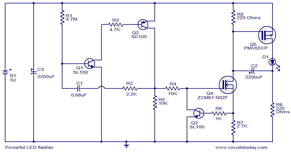
This circuit diagram illustrates a powerful LED flasher utilizing a 1W high power LED, which is widely available in the market. Transistors Q1 and Q2 are configured as an oscillator that generates positive pulses with a duration of 20...
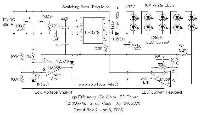
The heart of the circuit is a string of 10 white LEDs. These are wired in series and connected to a current-regulated step-up switching power supply circuit. DC powered LED lighting circuits can vary from the trivial, with a...
A highly practical workbench lighting unit designed for electronics hobbyists. The portable inspection lamp circuit features an onboard voltage regulator and a high-brightness 5mm white LED. It can be powered by any 9 to 18 volt DC-rated AC mains...
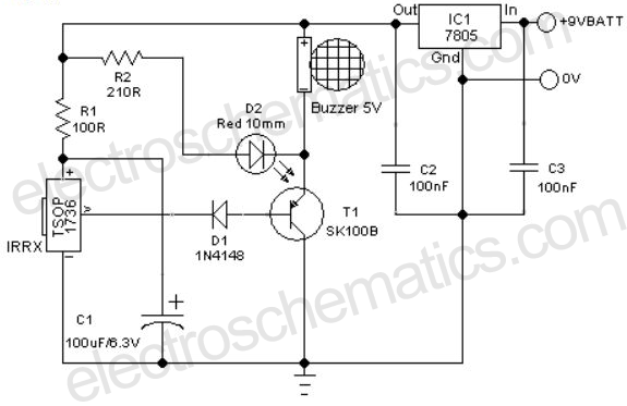
A remote-controlled alarm circuit utilizing the TSOP1736 is designed for easy use by elderly individuals or patients confined to bed. This battery-operated alarm system eliminates the need for routing electric cables to a calling bell switch, making it a...