
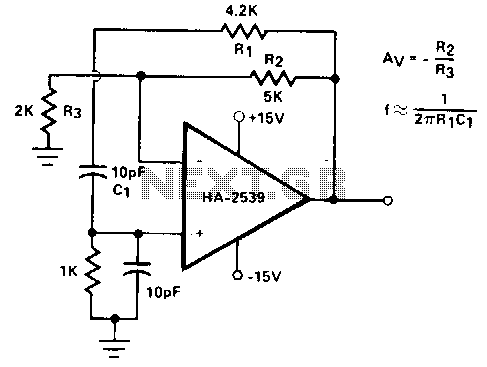
187 KHz RF oscillator
More: (a) The total input power to the final radio frequency stage (exclusive of filament or heater power) shall not exceed one watt.
(b) The total length of the transmission line, antenna, and ground lead (if used) shall not exceed 15 meters.
(c) All emissions below 160 kHz or above 190 kHz shall be attenuated at least 20 dB below the level of the unmodulated carrier. Determination of compliance with the 20 dB attenuation specification may be based on measurements at the intentional radiator's antenna output terminal unless the intentional radiator uses a permanently attached antenna, in which case compliance shall be demonstrated by measuring the radiated emissions.
If you are thinking seriously about building a Part 15 transmitter, I suggest you read through Part 15 to make sure you are fully compliant. The FCC provides for very heavy penalties for those who step out of line.
Here is where I found this copy of Part 15:
http://www.access.gpo.gov/nara/cfr/waisidx_02/47cfr15_02.htmll
I have known about the provision that allows 1 watt license-free operation on this band for a long time, but didn't really take it seriously. The maximum antenna length is only 15 meters. This is electrically very short compared to the 1600 meter wavelength and is therefore a very poor radiator.
However poor the efficiency of the antenna, some people using sophisticated coding and decoding techniques have managed to communicate over thousands of miles in this band (160 to 190 kHz), all operating within the scope of Part 15. Amazing.
In order to get started tinkering with circuits on this band, I put together a low power signal source.
This signal source only supplies a few milliwatts to the output stage when the +8V input is supplied by a 9V transistor radio battery. The low power in the output stage results from the collector load being a parallel tuned stage, thus it is a high impedance at resonance.
The circuit consists of several key components: an oscillator, a power amplifier, and a modulation stage, all of which are essential for generating RF signals at the specified frequency. The oscillator is typically based on a crystal or LC circuit that establishes the fundamental frequency of operation at 187.5 kHz.
The power amplifier stage is designed to boost the signal output to a sufficient level while adhering to the FCC regulations regarding power limits. The use of a small power stage ensures that the overall output does not exceed one watt, maintaining compliance with Part 15 guidelines. This stage may incorporate a transistor configured in a common emitter or common collector arrangement, depending on the desired gain and impedance characteristics.
Modulation is achieved using techniques such as amplitude modulation (AM) or frequency modulation (FM), depending on the application's requirements. The modulation circuit integrates with the oscillator to impose the desired signal characteristics onto the RF carrier frequency.
The loop antenna is designed to be compact and efficient for the low-frequency operation, although its performance may be limited due to its size relative to the wavelength. The antenna's characteristics can significantly influence the range and clarity of the transmitted signal, making careful design and tuning crucial.
To ensure compliance with FCC regulations, the total length of the transmission line, including the antenna and any ground leads, must not exceed 15 meters. Additionally, emissions outside the specified frequency range must be attenuated by at least 20 dB to prevent interference with other communications.
Overall, this low power RF signal source serves as an experimental platform for investigating receiver capabilities and exploring communication techniques within the constraints of the FCC Part 15 Lowfer band.An oscillator, a small power stage, some modulation, and a tiny loop antenna make RF for experiments on at 187.5 kHz on the United States' FCC Part 15 Lowfer band (1600-1750 meters). This is a low power signal source I put together one evening to provide 187 KHz RF signals for an anticipated receiver investigation.
Under Federal Communications Commission rules inside the United States, one is allowed to operate a transmitter without a license under certain conditions. Here, I have copied the relevant section of the most recent version of the Code of Federal Regulations that I could find..
(a) The total input power to the final radio frequency stage(exclusive of filament or heater power) shall not exceed one watt. (b) The total length of the transmission line, antenna, and ground lead (if used) shall not exceed 15 meters.
(c) All emissions below 160 kHz or above 190 kHz shall be attenuated at least 20 dB below the level of the unmodulated carrier. Determination of compliance with the 20 dB attenuation specification may be based on measurements at the intentional radiator's antenna output terminal unless the intentional radiator uses a permanently attached antenna, in which case compliance shall be demonstrated by measuring the radiated emissions.
If you are thinking seriously about building a Part 15 transmitter, I suggest you read through Part 15 to make sure you are fully compliant. The FCC provides for very heavy penalties for those who step out of line. Here is where I found this copy of Part 15: http://www.access.gpo.gov/nara/cfr/waisidx_02/47cfr15_02.htmll I have known about the provision that allows 1 watt license free operation on this band for a long time, but didn't really take it seriously.
The maximum antenna length is only 15 meters. This is electrically very short compared to the 1600 meter wavelength and is therefore be a very poor radiator. However poor the efficency of the antennat some people using sophisticated coding and dedecoding techniques have managed to communicate over thousands of miles in this band (160 to 190 kHz), all operating within the scope of Part 15.
Amazing. In order to get started tinkering with circuits on this band, I put together a low power signal source. This signal source only supplies a few milliwatts to the output stage when the +8V input is supplied by a 9V transistor radio battery.
The low power in the output stage results from the collector load being a parallel tuned stage, thus it is a high impedance at resonance. 🔗 External reference
Related Circuits
The circuit was designed to create an electronic oscillator known as the Wien Bridge Oscillator, which can be used for the generation of low-frequency sine waves. The Wien Bridge Oscillator is a type of electronic oscillator that generates sine waves....
Intended primarily as a building block for a QRI transmitter, this 20-MHz oscillator delivers a clean 6-V peak-to-peak signal into a 100-ohm load. The 20-MHz oscillator functions as a critical component in the design of a QRI transmitter, providing a...
This active antenna schematic can be used to frequency range from 10 KHz to 100 MHz. The length of the Antenna can be between 0.5 to 1 meter long. The power consumption is 20-30mA. More: Use the shortest possible...
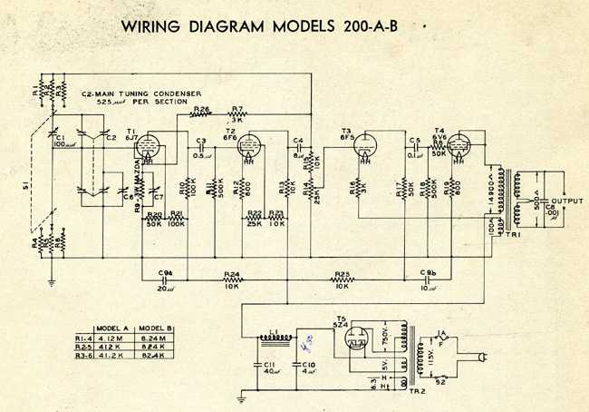
This is a resistance-tuned oscillator that operates in three frequency ranges from 35 cycles per second (cps) to 35,000 cps. A significant challenge with resistor/capacitor tuned bridges is maintaining a constant output level across a full decade frequency range....
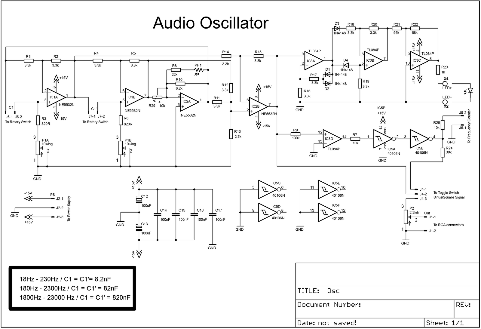
The project involves adding a DIY audio oscillator to a home workshop, which is essential for testing audio projects. While a basic oscillator is already available, it lacks a frequency counter. The design follows a schematic that provides a...
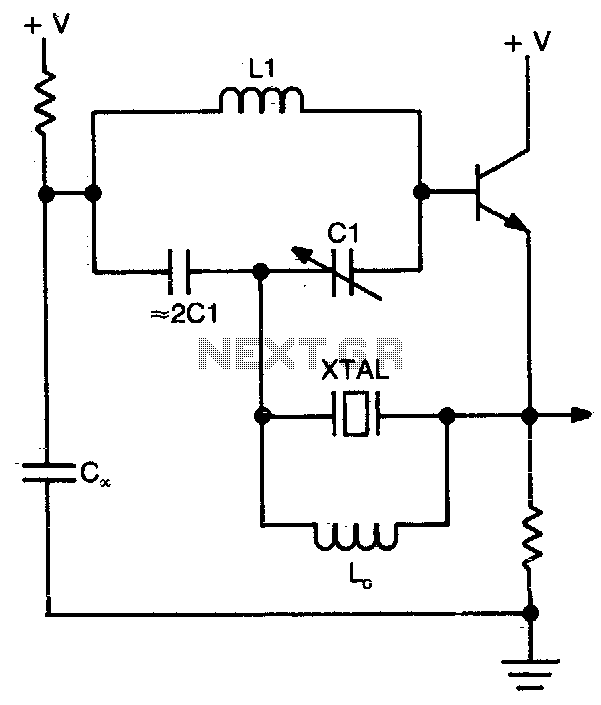
This circuit operates at or near series resonance. It is a well-designed circuit with no parasitics. It is easy to tune and has good frequency stability. The circuit in question utilizes series resonance to achieve optimal performance. At series resonance,...