
18v power supply using lm7818
The power supply circuit design begins with the AC mains input, which is typically at a voltage of 230V. The transformer steps this down to a lower voltage of 18V AC at a current rating of 2A. This transformer is essential for isolating the circuit from the high voltage AC mains and providing a safe operating voltage for the subsequent components.
Following the transformer, a diode bridge rectifier is employed to convert the 18V AC voltage into pulsating DC. The bridge consists of four diodes arranged in a configuration that allows current to flow in one direction, effectively converting both halves of the AC waveform into a usable DC output. The use of a 2A-rated diode bridge ensures that it can handle the maximum current flowing through the circuit without overheating or failing.
After rectification, the output voltage from the diode bridge is smoothed using a 2200µF electrolytic capacitor. This capacitor acts as a filter, reducing the ripple voltage present in the rectified output. The large capacitance value is chosen to ensure that the voltage remains stable under varying load conditions.
To protect the voltage regulator from potential feedback, a 1N4001 diode is placed in series with the output. This diode prevents any reverse current from flowing back into the regulator, which could cause damage or erratic behavior in the circuit.
The LM7818 voltage regulator is the core component of this power supply circuit. It is designed to provide a fixed output voltage of 18V DC with a maximum load current of 1.5A. The regulator features built-in protections such as thermal shutdown, which prevents overheating by shutting down the output if the chip exceeds a certain temperature threshold. Additionally, the internal current limiting feature ensures that the output current does not exceed the rated maximum, providing an extra layer of safety for both the regulator and the connected load.
For optimal performance, it is crucial to attach a suitable heatsink to the LM7818. The heatsink dissipates heat generated during operation, allowing the regulator to maintain its efficiency and reliability over time. Proper thermal management is essential, especially when operating close to the maximum current rating.
In summary, this power supply circuit is designed to deliver a stable 18V DC output with robust protection features, making it suitable for a variety of electronic applications requiring reliable voltage regulation.This power supply will work accurately where you have the need of stable 18V DC and provides current upto 1. 5A. The circuit is using a LM7818 positive voltage regulator IC. This IC has many built in features like internal current limiting, short circuit protection, thermal shutdown, safe area protection etc.
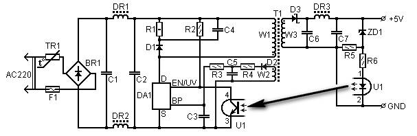
The 230V to 18V 2A transformer step dow n the mains voltage and the 2A diode bridge rectify the voltage and convert it to DC. The 2200uF capacitor fiters the voltage comming from the bridge diode. 1N4001 diode is used to block feedback to the IC. The Voltage regulator IC steps down the input voltage and provides 18V DC ouput. Use a suitalble heatsink with the IC. 🔗 External reference
Related Circuits
The amplifier drives a pair of speakers using two LM3876 amplifier chip circuits (50 watts per channel) or a pair of headphones with Meier Crossfeed through a clarifier and a dual OPA2134 Opamp. It features four selectable band inputs...

The board can now be tested. Set the DIP switch to Switch1 ON, Switch2 OFF (15-second delay), Switch3 ON, and Switch4 OFF (4 rings to activate half for switching ON). To switch ON relay 1 (connected to RB0 of...
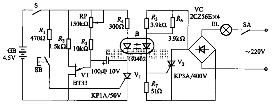
The circuit illustrated in Figure 2-48 consists of two configurations. Configuration 2-48 (a) operates using a 4.5V battery, while configuration 2-48 (b) employs AC capacitors to reduce the voltage supply. In configuration 2-48 (a), the delay time is influenced...
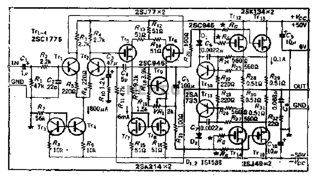
The circuit consists of three identical basic stages, with the second stage featuring a differential output from the power MOSFET, 2SJ77. A current mirror circuit utilizing 2SK214 is implemented. The operating current is 6mA; however, due to the power...
5 Volt/1.5A Switching Power Supply based on the TNY264P power supply. Refer to the designated page for an explanation of the related circuit diagram. The 5 Volt, 1.5A switching power supply utilizing the TNY264P is a compact and efficient power...
A constant off-time control that provides high efficiency over a wide range of output current can be utilized by the LT3463A dual micropower DC/DC converters with internal Schottky diodes, as detailed in the following circuit diagram and the datasheet. The...