
1994 Mercury Topaz Instrument Cluster Illumination Wiring Diagram
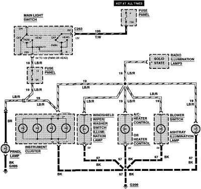
The 1994 Mercury Topaz instrument cluster illumination wiring diagram provides a detailed representation of the electrical connections and components responsible for the lighting system within the instrument panel. This diagram is essential for troubleshooting and repairing issues related to the illumination of the dashboard gauges and indicators.
The wiring diagram typically includes the following components:
1. **Power Source**: The diagram indicates the source of power, usually from the vehicle's battery or ignition switch, which supplies voltage to the illumination circuit.
2. **Dimmer Switch**: A dimmer switch is often integrated into the circuit, allowing the driver to adjust the brightness of the instrument cluster lights. The wiring diagram shows how this switch connects to the power source and the illumination bulbs.
3. **Illumination Bulbs**: The diagram details the placement of the illumination bulbs within the instrument cluster. It specifies the type of bulbs used and their connection points to the circuit.
4. **Ground Connections**: Proper grounding is crucial for the functionality of the lighting system. The wiring diagram illustrates the ground points that complete the circuit, ensuring that the bulbs operate correctly.
5. **Color Codes**: The wiring diagram may include color codes for the wires, aiding in the identification of each connection and facilitating easier repairs and modifications.
6. **Additional Components**: Depending on the complexity of the circuit, additional components such as fuses, relays, or connectors may be depicted, providing a comprehensive view of the instrument cluster's electrical system.
Understanding this wiring diagram is critical for automotive technicians and DIY enthusiasts when diagnosing lighting issues or performing upgrades to the instrument cluster in the 1994 Mercury Topaz. Proper interpretation of the diagram ensures accurate repairs and maintenance of the vehicle's electrical system.1994 Mercury Topaz Instrument Cluster Illumination Wiring Diagram. 🔗 External reference
Related Circuits
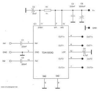
This is a 22-watt car stereo audio amplifier. The circuit is based on a single IC TDA1553 with a few peripheral components. This IC is designed for car audio applications. The TDA1553CQ integrates two 22-watt amplifiers with differential input...

A field effect transistor amplifier features a fixed bias input source with feedback, resulting in very high input impedance and low capacitance. It drives a field effect transistor or emitter follower, despite having a very low output impedance, utilizing...

Circuit diagram for a DC power supply protection circuit. The device includes a buck rectifier power supply, a monostable delay circuit, a relay control circuit, and an audio feedback oscillation circuit. The entire circuit operates with a DC voltage...
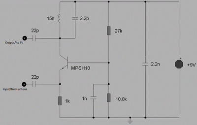
This circuit is designed to enhance RF signals from a television antenna operating at UHF frequencies in the range of 450-800 MHz. It provides a gain of approximately 10 dB, making it suitable for boosting weak TV signals. The...

The INA337 circuit, as illustrated, is part of a load current measuring shunt circuit. It generates a voltage drop across the sampling resistor Rs, which is connected in series between the power source and the load. The load current...

The power supply described utilizes a regulator composed of two NPN transistors. One transistor functions as the power regulator, while the other controls the output voltage. This power supply offers an adjustable output voltage range of 6-12 VDC. The...
Warning: include(partials/cookie-banner.php): Failed to open stream: Permission denied in /var/www/html/nextgr/view-circuit.php on line 713
Warning: include(): Failed opening 'partials/cookie-banner.php' for inclusion (include_path='.:/usr/share/php') in /var/www/html/nextgr/view-circuit.php on line 713