
simple booster tv schematic diagram
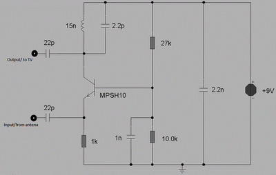
The RF amplifier circuit designed for UHF television signals employs a tuned circuit configuration to maximize signal strength and clarity. The core components include a 15 nH inductor and a 2.2 pF capacitor, which together form a resonant circuit. This configuration is critical for effectively amplifying signals within the specified frequency range of 450-800 MHz.
The gain of approximately 10 dB indicates that the circuit can significantly improve the reception of weak signals, which is particularly beneficial in areas with poor signal strength. The choice of components is essential; the inductor and capacitor must be precisely selected to ensure that they resonate at the desired frequency. The option to substitute the 2.2 pF capacitor with a 4.7 pF capacitor or a variable trimmer capacitor allows for fine-tuning of the circuit, enabling users to adjust the resonance frequency for optimal performance based on their specific signal environment.
The simulated frequency response, generated using the TINA software, provides valuable insights into the performance of the circuit. By sweeping an input signal of 20 µV across the frequency range of 400-800 MHz, the simulation offers a graphical representation of how the circuit responds to various frequencies. The measurement into a 1 kΩ load reflects realistic operating conditions, while the 75 Ω impedance of the frequency generator aligns with standard RF practices. This simulation serves as a predictive tool, allowing engineers to assess the circuit's effectiveness before physical implementation.
Overall, this RF amplifier circuit is a practical solution for enhancing UHF television signals, combining a simple yet effective design with adjustable components to cater to varying reception conditions.This is circuit that can be used to strengthen the RF signals from a television antenna work at UHF frequencies in the range 450-800MHz. It has a gain of around 10dB and is suitable for boosting weak TV signals The tuned circuit comprising the 15nH inductor and 2.
2pF capacitor resonate in the center of the UHF band. The 2. 2pF capacitor may be Exch anged for a 4. 7pF or a Trimmer capacitor of 2-6pF to improve results. The approximate frequency response is shown below. N. B. This is a simulated response using the TINA program produced by using a swept input 20uV swept over the frequency range 400-800MHz. Output was measured into a 1k source and the frequency generator has a 75ohm impedance. 🔗 External reference
Related Circuits
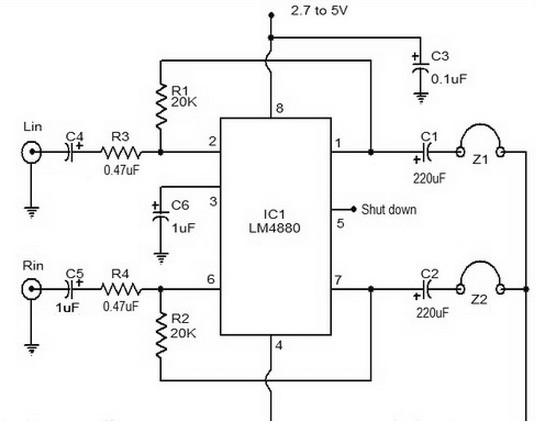
The LM4880 is a dual audio HiFi amplifier integrated circuit from National Semiconductor. This headphone amplifier circuit is specifically designed to produce high-quality audio output with a minimal number of components. The LM4880 integrated circuit is capable of delivering...
The heart of the PWM Fan Controller is a PIC 12F675 microcontroller. This microcontroller is reading the analog output of a LM35 temperature sensor using a ADC (analog to digital converter). The resulting digital value is converted to a...
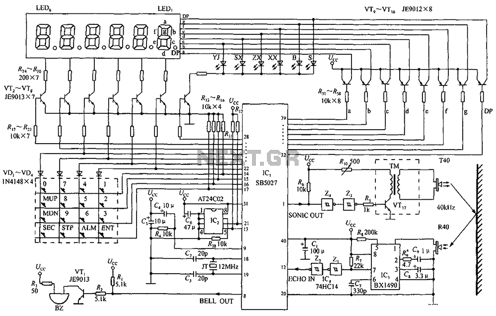
A circuit diagram of an ultrasonic range finder is constructed using a clock with a calendar and the Ultrasonic Ranging IC SB5027. The ultrasonic range finder circuit utilizes the Ultrasonic Ranging IC SB5027, which is designed to measure distances by...
A DIY GSM jammer schematic diagram designed specifically for GSM1900 frequencies ranging from 1930 MHz to 1990 MHz. The GSM1900 mobile phone network is utilized in the USA, Canada, and most South American countries. This cell phone jammer is...
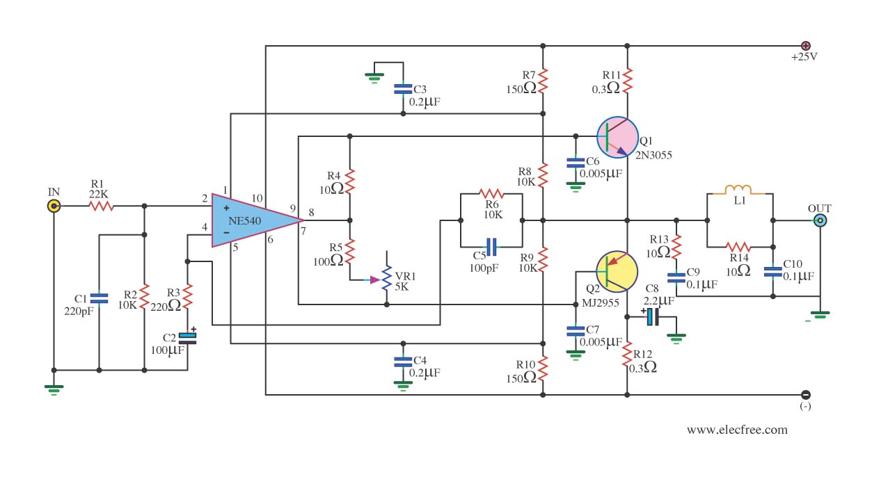
When the power supply reaches the circuit and the input signal is applied, the sound signal is processed through capacitor C1 and resistor R1 for signal coupling and noise reduction. The modified signal then reaches pin 3 (non-inverting) of...
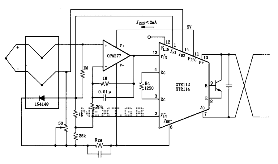
The OPA277 is configured as an inverting amplifier. This inverting amplifier utilizes high input impedance characteristics to minimize loop thermocouple offset drift. A 50-ohm potentiometer is included for calibration, allowing for the adjustment of the inverting input of the...