
sine to square triangle wave

The circuit design effectively transforms a sine wave input into both triangle and square wave outputs, utilizing a systematic approach to ensure signal integrity and stability across a wide frequency range. The choice of components, including the LM13700 and TL084, provides robust operational capabilities, while the use of potentiometers for amplitude control allows for versatile application in various electronic projects. The integration stage, facilitated by the transconductance amplifier and capacitor, is crucial for shaping the triangle wave, and the feedback mechanism involving resistors and capacitors is essential for maintaining precision in the output signal. The design's consideration of stray currents and offset voltages reflects a thorough understanding of the challenges associated with high-precision signal processing. Overall, this converter serves as a practical solution for generating triangle and square waveforms from a sine wave source, enabling a range of applications in electronics where such waveforms are required.If you need a triangle wave signal or a square one but you only have a sinewave generator, use this converter to avoid the trouble of beginning from scratch. It is made up of two ICs: one LM13700 and one TL084. The amplitude of the squarewave can be varied through P1 while potentiometer P2 varies the amplitude of the trianglewave signal.
The conve rter can process signals from 6 Hz up to 60 kHz. In many function generators, a triangle wave generator (which is usually made of a schmitt-trigger combined with an integrator) is the heart of the circuit. The resulting sine wave is then synthesized from the triangle wave with the help of special diode networks.
The circuit featured here, however, does it the other way around. First, the sinewave is reshaped to a triangle. Finally, the triangle is reshaped to a square wave. The sinewave is, however, not generated by this circuit. Therefore, you must get it from a sinewave source. The sinewave is reshaped by the opamp IC1A. The two resistors R3 and R4 reduce the output level of the IC1A, since this output level swings back and forth from negative 15 volts to positive 15 volts. The signal coming from IC1A is integrated by the combination of the transconductance amplifier IC1 and capacitor C2.
The integration time factor can be easily adjusted with a preset voltage level fed to pin 1 of IC1. The opamp IC2B is added to the circuit to act as an impedance converter. It prevents voltage shifts at the capacitor C2 that might happen due to overloading. The trianglewave can be sampled right from the output of IC2B. The following IC2C compares the trianglewave s amplitude with the value which is preset through P2. The output of IC2C controls the current regulator at the output of IC1A. This technique guarantees that the amplitude of the output signal remains independent from the input signal s frequency. The resistor R6 combined with the capacitor C1 play together so that the output level exactly matches the level that was preset by R4.
They are connected in a feedback manner. This technique solves the very common problem with high precision integrators - the sensitivity to offset voltages and stray currents. For example: a stray current (maximum: 7mA at 75 °C) can cause a slight change at the output signal. We want the resulting square wave to remain clean. That is why it is important the triangle wave must remain clean. To achieve it, the time constant of the RC circuit is selected to be high. This guarantees that the triangle wave can never influence the waveform to be integrated even at the lowest frequency levels.
This converter can process signals from 5 Hz with amplitude shifts of 0% up to 60 kHz with amplitude shifts of minus 10%. At higher frequencies - above 1 kHz - the circuit needs a longer time to stabilize itself. This is due to the high time constant levels of the RC circuits. You must set the maximal amplitude of the source signal to 1 volt. You can also use a battery to power the circuit since the current consumption is around 10 mA only. 🔗 External reference
Related Circuits
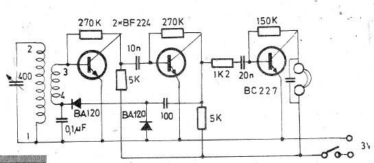
Oscillating circuits (coils) are constructed on a ferrite bar. For long wave reception, winding "1-2" consists of 135 turns, while winding "3-4" consists of 20 turns. For medium wave reception, winding "1-2" has 75 turns, and winding "3-4" has...
The NI 655X is a versatile high-speed digital product capable of interfacing with various technologies. This application note illustrates how to connect the NI 655X to Low Voltage Differential Signaling (LVDS) devices. LVDS is an emerging differential digital standard...
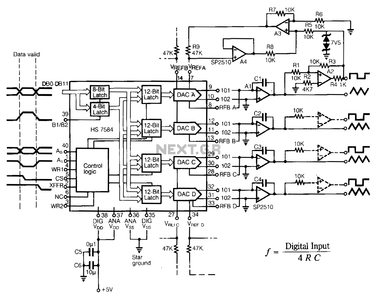
The programmable multiple output generator provides control signals for the data converter automated test equipment (ATE). Major performance criteria include simple interfaces with various microprocessor systems, low power consumption, stable output timing relationships, and minimal board space requirements. For...

This oscillator circuit is designed to generate both a rectangular wave and a triangle waveform, operating within the frequency range of 1 kHz to 10 kHz. The first operational amplifier in the configuration produces the square wave, while the...
A PLL (Phase-Locked Loop) oscillator is utilized to achieve a very stable frequency with minimal distortion in the sine wave output. Its stability is comparable to that of crystal-based oscillators, while the distortion level of the sine wave output...
A precision half-wave rectifier utilizing an operational amplifier will achieve a rectification accuracy of 1% from DC to 100 kHz. A precision half-wave rectifier circuit is designed to convert an AC signal into a unidirectional output while maintaining high accuracy...