
1Mhz fet crystal oscillator
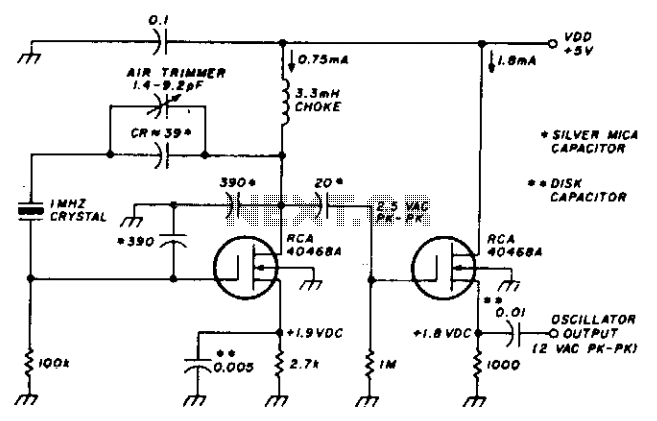
The described oscillator circuit is designed to maintain a consistent frequency output with minimal variation, specifically less than 1 Hz, across a supply voltage (VDD) range of 3 to 9 volts. The choice of MOSFET devices is crucial for achieving this stability, as they offer high input impedance and low output capacitance, which contribute to the circuit's overall performance. MOSFETs are known for their fast switching capabilities and low power consumption, making them ideal for oscillator applications where efficiency and precision are paramount.
In addition to the MOSFETs, the circuit employs stable capacitors, which play a significant role in determining the oscillator's frequency and stability. Capacitors with low temperature coefficients and minimal leakage current are preferred, as they ensure that the frequency remains unaffected by environmental changes or aging effects. The combination of these components results in a robust oscillator design that can reliably operate across a wide voltage range.
The oscillator's design may also include feedback mechanisms to enhance stability further. Negative feedback can be utilized to correct any frequency drift that may occur due to variations in supply voltage or component tolerances. This feedback loop can be implemented using additional resistive or capacitive elements, ensuring that the output frequency remains tightly regulated.
Overall, the oscillator circuit's resilience to voltage fluctuations and its ability to maintain a consistent output frequency make it suitable for various applications, including signal generation, clock pulses for digital circuits, and timing applications in microcontroller systems.This stable oscillator circuit exhibits less than 1 Hz frequency change over a VDD range of 3-9 volts. Stability is attributed to the use of MOSFET devices and the use of stable capacitors. 🔗 External reference
Related Circuits
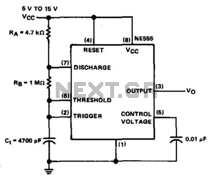
The NE555 timer is configured in astable mode and utilizes three timing components (RA, RB, and Ct). A 0.01 µF bypass capacitor is connected to pin 5 to enhance noise immunity. The operational limitations of the astable mode are...
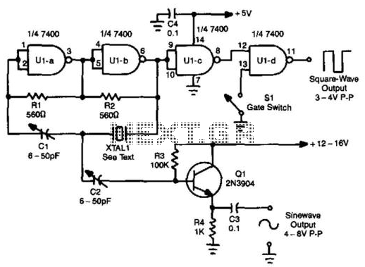
A TTL oscillator utilizing a Quad NAND Gate can operate with fundamental crystals ranging from 1 to 10 MHz. The sine wave output is derived directly from the crystal, which functions as its own filter, producing a relatively clean...
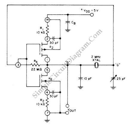
This circuit is a 2 MHz crystal oscillator utilizing a CMOS transistor pair. It is particularly suitable for applications in digital watches and clocks due to its low power consumption. The oscillator is constructed by connecting a CMOS transistor...
This is an operational amplifier (Op-Amp) oscillator circuit. This circuit has several advantages, including its ability to operate at low frequencies. The operational amplifier oscillator circuit is designed to generate a periodic waveform output, typically a sine or square wave,...
The Hartley oscillator is an enhancement of the Armstrong oscillator. While its frequency stability is not the highest among oscillators, it is capable of generating a broad spectrum of frequencies and is straightforward to tune. The Hartley oscillator operates...
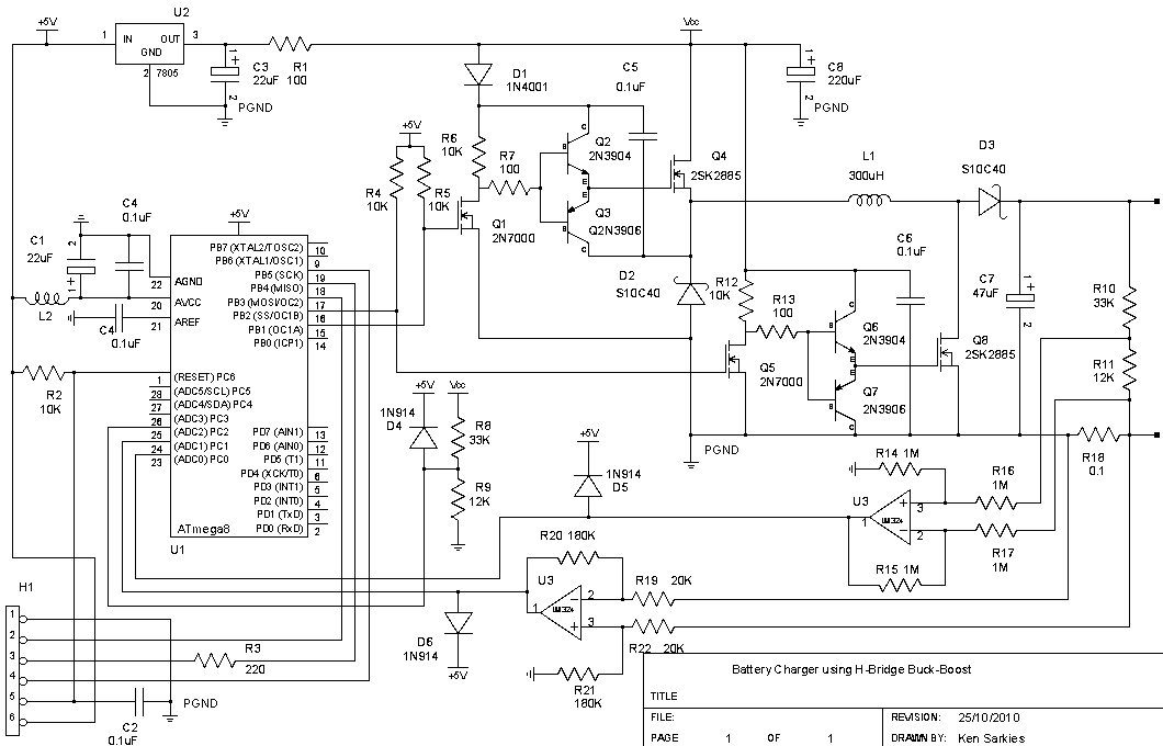
The buck-boost converter is valuable when the output and/or input voltages fluctuate significantly, necessitating the use of a buck converter at times and a boost converter at others. An example, which will be elaborated on in a future project,...