
A Half Bridge Buck Boost Converter with high side N-type MOSFET
The buck-boost converter serves as an essential component in applications requiring voltage regulation where input and output voltages can vary widely. Its ability to adaptively switch between buck and boost modes allows for efficient power management, especially in battery charging scenarios. The simplest configuration, comprising a single inductor, MOSFET, catch diode, and filter capacitor, exemplifies a straightforward approach. However, more complex topologies, such as the H-Bridge, offer enhanced functionality by allowing synchronous operation of the buck and boost stages.
In the H-Bridge design, the independent control of buck and boost sections is critical, necessitating careful consideration of timing and switching sequences to optimize efficiency. The use of logic-level n-channel MOSFETs facilitates lower on-resistance, thereby reducing conduction losses. The incorporation of Schottky diodes further enhances the performance by minimizing voltage drops during reverse conduction, which is vital in maintaining high efficiency in power conversion.
The control strategy for the H-Bridge must account for various operational states, and while some designs suggest excluding certain states to streamline control, simulations indicate that such exclusions may not yield significant efficiency benefits. This insight underscores the importance of thorough testing and validation in the design process to ensure optimal performance across varying load conditions.
Overall, the buck-boost converter's versatility and adaptability make it an invaluable asset in modern electronic systems, particularly in applications where power supply stability and efficiency are paramount.The buck-boost converter is of value where the output and/or input voltages vary to such an extent that on occasions a buck converter is needed, while on other occasions a boost converter is needed. An example (that will be described further in another project) is that of a battery charger for a number of different battery types, voltages and capa
cities and powered by a 12V source. The simplest buck-boost circuit uses a single inductor, MOSFET, catch diode and filter capacitor. This circuit is non-isolating and inverting. Other non-isolating buck-boost circuits include the †uk, which is inverting, and the Sepic, which is non-inverting. These circuits require two inductors which need not be coupled, although coupled inductors can provide much lower output ripple.
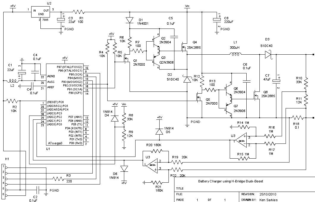
A disadvantage of these circuits is that they require a coupling capacitor which must be able to support high ripple current. The H-Bridge circuit provides a buck-boost function using a single inductor and without inversion. This is essentially a buck converter followed by a boost circuit. Since the former has its inductor is at the output while the latter has the inductor at the input, they may be replaced by a single inductor.
A filter capacitor is not present in the buck part of the circuit. The control of this circuit involves separate control of each section, and as such tends to be somewhat complicated. A number of companies produce controller chips for this type of circuit, including Linear Technology (eg LTC3780, LTM4607).
The H-Bridge is so called because the MOSFETs form the sides of an H with the inductor as the crossbar. In this form the buck and boost parts of the circuit are operated in synchronous mode (second diagram below).
It is also possible to operate the circuit non-synchronously using catch diodes in place of two of the MOSFETs as shown in the first diagram, with associated simplification of the circuit and its control. Such a circuit is described in reference 3 below. This circuit is commonly described as a classic buck-boost converter, although useful Internet references for this circuit are rare.
Reference 2 gives a good description of the drawbacks of the circuit, most of which focus on its efficiency, and high inductor and capacitor current. The way they suggest to overcome this is to place the circuit into either buck or boost mode depending on the input voltage, with a buck-boost mode near the point where the output and input voltages are the same.
Reference 3 discusses a control scheme wherein the buck and boost sections are controlled by different circuit state variables. They investigate efficiency against the relative phase of the switching of each section, and show that it varies little if at all regardless of the phase difference.
We provide a more detailed theoretical and simulation investigation of the H-bridge buck-boost converter to illuminate the modes of operation and to determine estimates of efficiency. Reference 3 refers to a control chip by STL Electronics for the H-bridge circuit. The authors insist that one of the four states of the two switches should be excluded. This makes the control algorithm rather complex. No justification for this is given other than that it doesn`t occur in either the buck or boost circuit states.
Our simulations indicate that any efficiency gains from applying this restriction are incidental and appear to be small. The MOSFETs are logic level n-types that were scrounged out of old computer motherboards, and can be replaced with other suitable low voltage, low on-resistance types.
These particular MOSFETs have an on-resistance of about 20m © at 10V gate-source voltage. The Schottky diodes were also scrounged out of old equipment and can handle 10A forward current. The drive circuitry has already been discussed in earlier SMPS projects. The drive circuit for the upper MOSFET uses a charge pump to raise the MOSFET gate voltage above the 🔗 External reference
Related Circuits
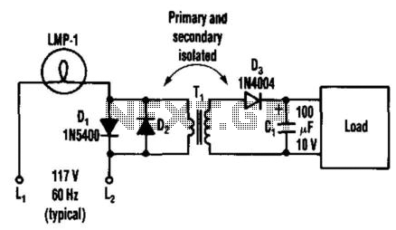
By connecting two back-to-back diodes in series with an AC power circuit, a voltage of approximately 1.4 Vpp can be achieved. This voltage is beneficial for energizing the primary coil of a small transformer. The voltage induced in the...
The completed board may be driven by voltages between 0.8 and 3 Volts. While the basic design goal was candle-like light from a single cell, the values used were chosen to allow safe operation from 3 Volts so you...
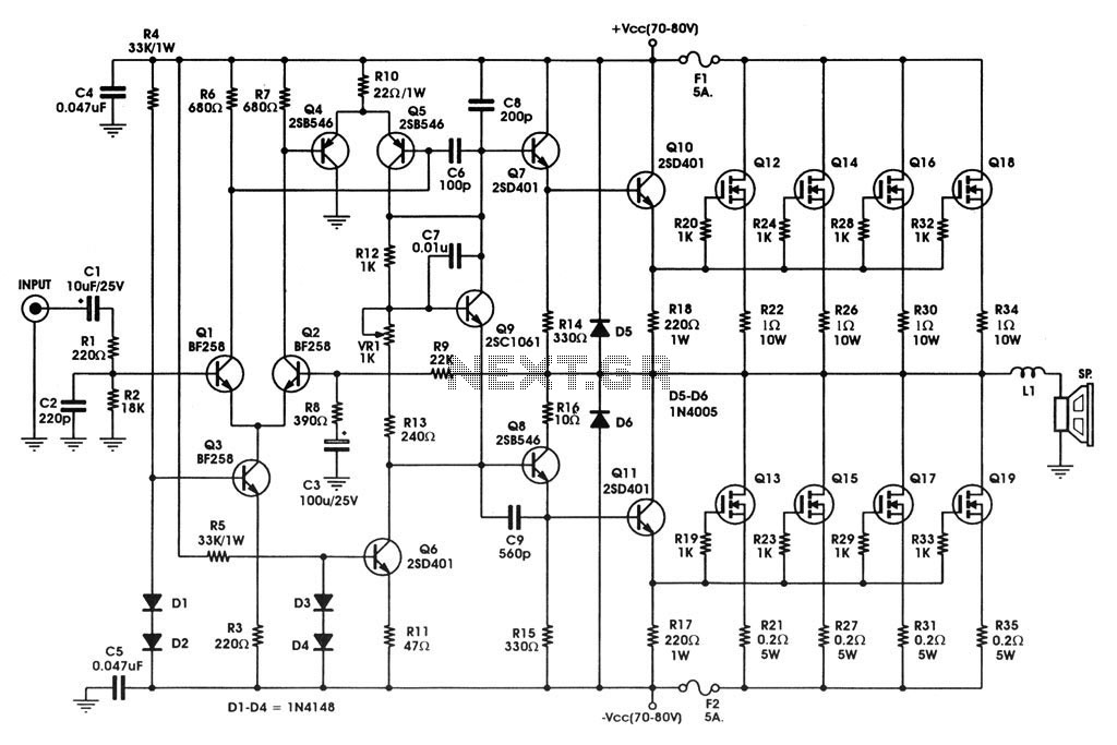
400 W MOSFET Audio Amplifier circuit using IRFP448. This circuit is categorized under amplifiers and includes five circuit diagrams. For more detailed information, refer to the main post titled "400 W MOSFET Audio Amplifier Using IRFP448." This post also...
In applications where a MOSFET is employed to switch a load, incorporating short-circuit or overload protection is straightforward. This can be achieved by utilizing the internal resistance RDS(ON) of the MOSFET, which generates a voltage drop proportional to the...
This cost-effective circuit can be connected to an air conditioner, refrigerator, or any other advanced electrical appliance for protection. This circuit serves as a protective device for sensitive electrical appliances such as air conditioners and refrigerators. It is designed to...
Switched-capacitor filters that are preset for a given bandwidth sometimes do not deliver the bandwidth or Q an application requires. By inverting the clock between two switched-capacitor bandpass filters, such as the MSFS1 from Mixed Signal Integration Corp, you...