
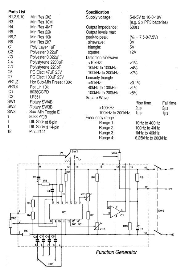
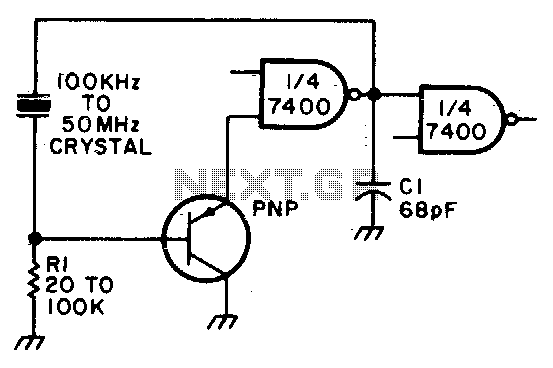
Sine- And Square-Wave Ttl Oscillator

The described circuit employs a Quad NAND Gate integrated circuit, which provides flexibility in generating both sine and square wave outputs. The fundamental frequency of oscillation is determined by the crystal resonator, which operates within the specified range of 1 to 10 MHz. The crystal not only sets the frequency but also acts as a low-pass filter, ensuring that the output sine wave is free from significant harmonic distortion.
Capacitors CI and C2 play a crucial role in fine-tuning the oscillator's performance. CI is typically connected in parallel with the crystal to stabilize the oscillation and enhance the purity of the sine wave output. C2 is often used for feedback purposes, affecting the phase shift necessary for sustained oscillation. The optimal values for these capacitors depend on the specific crystal used and may require empirical adjustments to achieve the desired waveform characteristics.
The TTL square wave output from U1D can be utilized in various applications, including digital signal processing and clock generation for microcontrollers. The square wave signal is characterized by its sharp transitions and can be easily interfaced with other digital logic circuits.
To facilitate electronic control of the output, the gate switch in the circuit can be replaced with a logic gate. This modification allows for integration with other digital systems, enabling the oscillator's output to be turned on or off based on logic levels. Such versatility enhances the circuit's applicability in automated systems and programmable devices.
Overall, this oscillator circuit is an effective solution for generating stable sine and square wave signals, suitable for a range of electronic applications. Proper component selection and adjustment are essential for achieving optimal performance. Using a Quad NAND Gate, the TTL oscillator can use fundamental crystals between 1 and 10 MHz. The sine -wave output is taken directly from the crystal, which acts as its own filter, and yields a fairly clean sine wave. Adjust CI and C2 for the best sine wave and also to set the crystal frequency. TTL square wave can be taken from U1D. The gate switch can be replaced with a logic gate to electronically control the output.
Related Circuits
This generally results in a square wave if the frequency of oscillation is low enough relative to the amplifier's bandwidth. The schematic of a crystal-controlled oscillator features a low-frequency sine wave oscillator characterized by low distortion, wideband operation, and...
Adjust Rl for approximately 2 volts at the output of the first gate. Additionally, adjust Cl for optimal output. In the context of electronic circuit design, the output voltage of a gate, such as a logic gate or operational amplifier,...
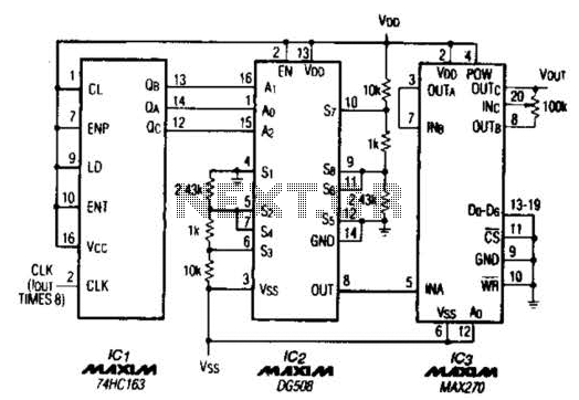
A TTL counter, an 8-channel analog multiplexer, and a fourth-order low-pass filter can generate sine waves ranging from 10 kHz to 25 kHz with a total harmonic distortion (THD) better than -80 dB. The circuit employs two cascaded second-order,...
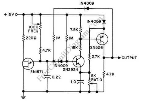
A discrete oscillator circuit illustrated in the schematic diagram below is a variable duty cycle and variable frequency oscillator, which can be utilized to generate various output waveforms. The discrete oscillator circuit is designed to produce oscillations with adjustable frequency...

Edwin Henry Colpitts was a communications pioneer best known for his invention of the Colpitts oscillator. As research branch chief for Western Electric in the early 1900s, he and scientists under his direction achieved significant advances in the development...
A type of relaxation oscillator comprising two stages that are interconnected such that the input of one stage is derived from the output of the other. This configuration essentially consists of two amplifiers cross-coupled with regenerative feedback in its...