
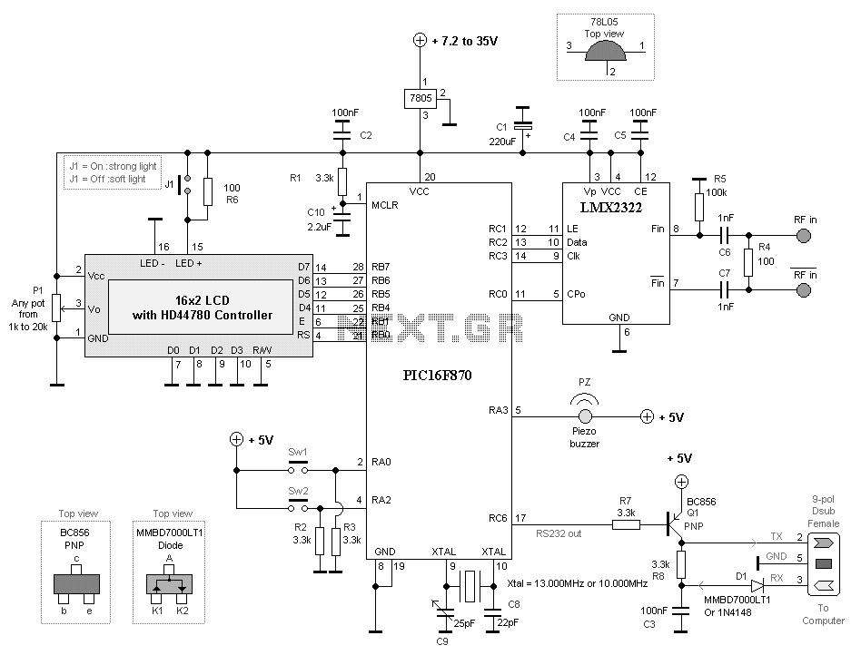
2.5 GHz Frequency meter with 2x16 LCD display
When a 13 MHz crystal is used, the calibration of the counter is made by the variable capacitor C9. It will be able to change the timing ±100 ppm (±10 kHz at 100 MHz). Most people do not have a good reference to calibrate against, making it a bit difficult. The frequency counter is designed to be a measuring tool with good accuracy.
A "poor man calibration" can be performed using a good TCXO or similar with good frequency tolerance. A VCTCXO 12.800 MHz Crystal Oscillator manufactured by NDK (NKG3001B) has been tested, which has ±2.5 ppm tolerance. This oscillator is connected to the input pin 11 (RC0) of the PIC. Feeding the input with 12.8 MHz simulates an input RF signal of 1,638,400,000 Hz. The display should now show 1,638,400,000 Hz. Tuning C9 until this value is reached on the display results in a frequency counter with an accuracy of ±2.5 ppm (±250 Hz at 100 MHz).
The frequency counter circuit integrates several critical components to ensure accurate frequency measurements. The PIC16F870 microcontroller serves as the central processing unit, managing input from the frequency source and controlling the LCD display for output. The prescaler LMX2322 allows the counter to handle high-frequency signals up to 2.5 GHz, enhancing its measurement capabilities.
The LCD interface is designed for ease of use, featuring a two-line, 16-character display that presents frequency readings and menu options. The 4-wire connection mode to the PIC allows for efficient communication and control of the display. The variable capacitor C9 is crucial for calibration, enabling fine-tuning of the frequency counter's accuracy.
The design also includes user-friendly features such as a menu system navigated by switches SW1 and SW2, allowing users to select reference frequencies and access various functions. The option to connect an external 10 MHz reference signal provides flexibility for users seeking enhanced accuracy with external oscillators.
Overall, this frequency counter project combines a robust hardware design with versatile software capabilities, making it a valuable tool for various applications in electronics and signal measurement.This project explain a very powerful frequency counter which has many useful software functions. The software can add or subtract 3 different IF frequencies (±455 kHz ,±10.7 MHz and ±21.4 MHz). You have also two level of resolutions, 1kHz and 100Hz. The main oscillator can be on-board 13MHz or external 10 MHz. The counter data can easy be transmitted to computer with RS232 cable. The counter is based around a LCD display with 2 lines and 16 chars. I have used a HD44780 based display which is very common. A PIC16F870 circuit controls all counting and display functions. A prescaler is added to make it possible to measure up to 2.5GHz with high sensitivity. The Display Module Size (W x H x T): 80mm X 36mm. The controller PCB has the same size. This makes the unit very small and slim. In the menu system of this frequency counter, you can choose between two reference frequencies. On-board 13.000MHz crystal (picture at right), or External 10.000MHz signal. The reason of using a external 10.000 MHz reference frequency is because it is common among reference oscillators, as HP Z3801 GPS locked frequency source. The main part of this project is a LCD, PIC16F870 and a prescaler LMX2322. The LCD is a standard 2 line 16 chars display connected in 4-wire mode to the PIC. At the bottom you will find a 13.000 MHz or external 10.000 MHz frequency connected to the PIC. Capacitor C9 is variable and is used to calibrate the Frequency counter. If you have an external 10 MHz oscillator you should remove the crystal, C8, C9 and connect the signal to pin 9 of the PIC16F870.
At pin 5 you have an output. It can be connected to a piezo buzzer or equal to generate a beep whenever any button is pressed. If you don't want to use it, you can leave this pin as it is. Pin 2 is the switch SW1 which you can toggle choices in the menu system. Pin 4 is the switch SW2 which guide you through a seven stages menu system. When a 13 MHz crystal is used, the calibration of the counter is made by the variable capacitor C9. It will be able to change the timing ±100ppm (±10kHz at 100MHz). Most people has no good reference to calibrate against and then it is a bit difficult. The frequency counter is supposed to be a measuring tool with good accuracy. One thing you can do is a "poor man calibration". You can use a good TCXO or equal with good frequency tolerance. I do have tested VCTCXO 12.800 MHz Crystal Oscillators manufactured by NDK (NKG3001B) which I have on my component page and it has ±2.5 ppm tolerance. I connect the 12.8 MHz ±2.5 ppm to the input pin 11 (RC0) of the PIC. Since I feed the input with 12.8MHz, I simulate an input RF signal of 1,638,400,000 Hz. The display should show now show 1,638,400,000 Hz. All you need to do is to tune C9 until you reach that on the display. Now you have frequency counter where the accuracy is ±2.5ppm (±250Hz at 100MHz). 🔗 External reference
Related Circuits
A schematic diagram of the oscillator is presented in Figure 1. The common-base transistor stage (Q1) amplifies the signal within the positive feedback loop. The positive feedback signal develops across the resistor R1, which is shared by the emitters...
The PSoC 3 Primer Kit is specifically designed to assist students in mastering the necessary skills in embedded systems. The kit is structured to enable easy utilization of all possible features of the microcontroller. It supports the FX2LP Programmer,...
The circuit illustrated is a straightforward digital frequency meter that displays the frequency in hertz of an astable 555 timer. It may potentially be modified for alternative applications. An NPN transistor, TR2, is linked to the 555 astable timer...
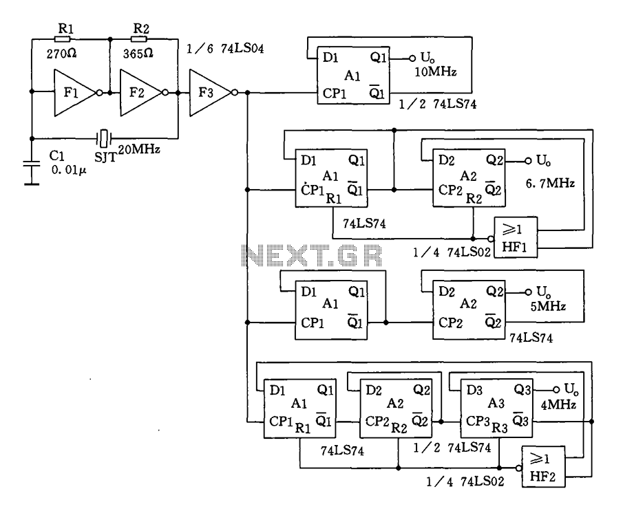
Crystal oscillator and frequency divider (74LS04) circuit diagram. The circuit diagram for a crystal oscillator combined with a frequency divider utilizing the 74LS04 integrated circuit is designed to generate a stable clock signal. The crystal oscillator component typically consists of...
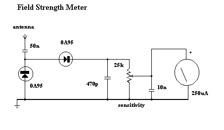
Because it uses few parts, a printed circuit board is not necessary; components can simply be soldered to one another. However, a box is desirable for operating convenience. The case and aerial from a discarded toy walkie-talkie was used...
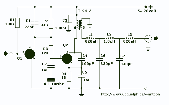
This transmitters' intended purpose is for morse-code only in the 30 meter band (10Mhz). It is a low-power QRP type and needs to be connected to your existing tranceiver. The harmonic rejections on the prototype were measured at 40dB...