
2 Kw flasher with photoelectric control
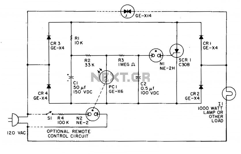
An alternative remote control can be created by adding a second neon lamp, N2, and masking the photocell so that it only detects N2. This configuration provides a highly sensitive remote control that is completely isolated from the load circuit. For low-voltage remote control, a flashlight lamp may be used in place of N2, operated at about half its normal voltage to achieve an exceptionally long lifespan. The performance of the photoelectric control can be inverted (causing it to flash when the photoconductor is illuminated) by swapping PCI and R2. Sensitivity in either the normal or inverted modes can be reduced by partially masking PCI and can be increased by raising the value of resistor R2 to approximately 470 K. To extend the on time, the capacitance of CI can be increased; to prolong the off time, the resistance of R3 can be increased.
The described circuit utilizes a bridge rectifier configuration with four diodes (CR1 to CR4) which enables efficient conversion of AC to DC. The silicon-controlled rectifier (SCR) serves as a switch that controls the discharge of capacitor CI. The photoconductor PCI plays a critical role in sensing light levels, which directly influences the charging and discharging cycles of CI. The inclusion of the neon lamp and its interaction with the circuit allows for visual indication of the circuit's operation, enhancing usability.
In the remote control application, the masking of the photocell ensures that it only responds to the designated neon lamp, which can be particularly advantageous in environments with multiple light sources. The option to use a flashlight lamp instead of a neon lamp for low-voltage applications demonstrates versatility in component selection, allowing for a balance between performance and longevity.
Adjustments to the circuit can be made to tailor its response characteristics. For instance, modifying R2 affects the sensitivity of the control, allowing for adaptability to different lighting conditions. Similarly, the timing of the on and off states can be fine-tuned by altering the capacitance of CI and the resistance of R3, providing flexibility in the circuit's operational parameters.
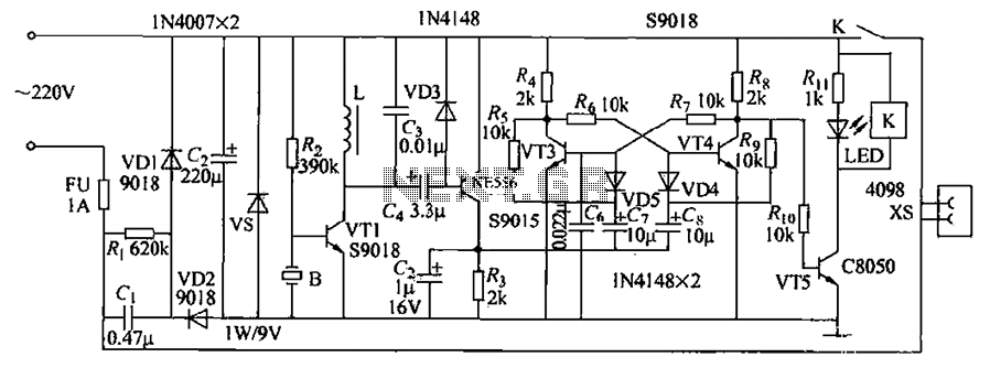
Overall, this circuit exemplifies a sophisticated integration of light sensing and control mechanisms, suitable for various applications requiring remote operation and light sensitivity.CR1, CR2, CR3, and CR4 form a bridge circuit with the SCR across the dc legs. With light on the photoconductor PCI, CI charges through Rl to about 150 Vdc. The resistance of PCI is low when illuminated, so very little voltage appears across it or C2. At about 90 volts CI starts discharging through Rl and the SCR, but the SCR cannot turn off until CI is almost completely discharged. When the SCR turns off during the interval line voltage is near zero, the full supply voltage again appears across the bridge, and Cl charges again to a high voltage.
The voltage on C2 also starts rising until the neon lamp fires and the cycle repeats. An alternative remote control can be made by adding a second neon lamp, N2, and masking the photocell so it sees only N2. A very sensitive remote control is thus obtained that is completely isolated from the load circuit. For low-voltage remote control a flashlight lamp may be used instead of N2 and operated at about Vi its normal voltage thus giving exceptionally long life.
Performance of the photoelectric control may be inverted (flash when the photoconductor is illuminated) by interchanging PCI, and R2. Sensitivity in either the normal or inverted modes can be decreased by partially masking PCI, and can be increased by increasing resistor R2 to about 470 K.
To increase on time, increase Cl; to increase off time, increase R3. 🔗 External reference
Related Circuits
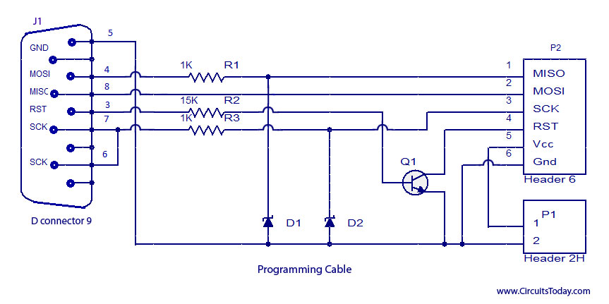
ISP programmer with circuit diagram for AVR Atmega32 microcontroller. This ISP burner circuit is an adaptation of the Pony programmer and uses PonyProg software. The ISP (In-System Programming) programmer designed for the AVR Atmega32 microcontroller allows for programming the microcontroller...
A voltage-controlled oscillator (VCO) is an electronic signal generator that produces a signal with a variable frequency, which is dependent on an input voltage level. A voltage-controlled oscillator is a fundamental component in various electronic applications, including phase-locked loops (PLLs),...

The microcontroller design features the microcontroller (MCU) in hibernation mode, which can only be awakened by a pulse (high-low-high) signal on the reset pin (active low). An accelerometer or an external real-time clock (RTC) serves as the wake-up source....
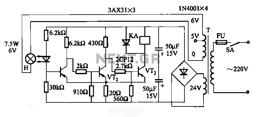
JG series of photoelectric relay circuit. To ensure reliable operation, a Schmitt trigger circuit has been incorporated. These circuits function similarly; when light strikes the photosensitive component, its internal resistance decreases, activating the transistor VT and subsequently energizing the...
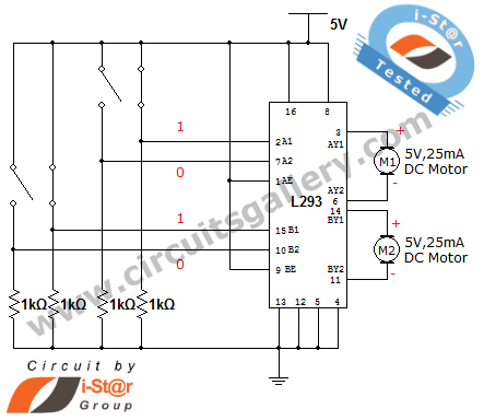
How can a DC motor be rotated in clockwise and counterclockwise directions? This is a common question posed by many robotics beginners. DC motor driver circuits are essential components in robotics workshops. The L293D IC is frequently utilized for...
Asia ultrasonic remote control switch. This example describes the use of a gas pressure bisulfite ultrasound flute (made of rubber, available in olive and flat round shapes) for control. When the ultrasonic flute is activated, the remote control switch...