
microcontroller Generate a reset signal from a falling edge trigger

In this microcontroller design, the MCU is optimized for low power consumption by employing hibernation mode, significantly extending battery life in portable applications. The wake-up mechanism is crucial, relying on a specific pulse sequence on the reset pin to transition the MCU from hibernation to operational mode.
The accelerometer and RTC serve as interrupt sources. When motion is detected by the accelerometer or a time event occurs in the RTC, they pull their respective interrupt pins low. However, these interrupts alone do not trigger the MCU wake-up. Instead, a logic circuit is required to convert these low signals into a single high-low-high pulse for the reset pin.
To achieve this, a monostable multivibrator (one-shot timer) can be employed. When the interrupt pin goes low, the multivibrator can be configured to generate a single pulse of a predetermined duration on its output. This output pulse can then be connected to the reset pin of the MCU. The pulse width must be carefully chosen to ensure that it meets the timing requirements of the MCU's reset specifications.
Additionally, a D flip-flop can be used in conjunction with the interrupt signal to create the necessary toggle effect. The flip-flop can be clocked by the interrupt signal, and its output can be configured to produce a high-low-high signal when the interrupt is asserted. This setup ensures that the reset pin receives the toggle pulse only once, preventing any unintended multiple resets.
The design also needs to incorporate a mechanism for the MCU to clear the interrupt status from the accelerometer and RTC. This is typically done by reading specific registers in these peripherals; thus, the MCU must transition to its operational mode to perform this action. The system architecture should ensure that upon waking, the MCU is programmed to handle the interrupts effectively, resetting the state of the peripherals and returning to hibernation mode after processing the necessary tasks.
Overall, this design efficiently combines low-power operation with responsive wake-up capabilities, leveraging interrupt-driven mechanisms and logic circuits to facilitate a seamless transition between sleep and active states.Microcontroller design where the mcu is placed in hibernation mode, and can only be awoken by a pulse(high-low-high) signal on the reset pin. (active low) As a wake-up source i`m using an accelerometer or an external RTC. The idea is to have the accelerometer trigger an interrupt, that drives an interrupt pin low. The same goes fo r the RTC. It will pull an interrupt pin to logic low signal. However, this won`t wake the mcu from hibernation mode. I need to use this sleep-mode to save as much power as possible. I`m wondering how I can create a toggle signal from the interrupt-pin signal form the wakeup sources. The toggle must only happen once, since its the reset-pin of the mcu. Is there any kind of latches of logic circuits/components that create this kind of signal Edit2: The interrupt signals from both accelerometer and RTC stays low until reset by mcu.
Usually this is done by reading a register in the peripheral unit. And for this to happen the mcu must be awake. 🔗 External reference
Related Circuits

A high-frequency signal is displayed in the output amplifier. The circuit consists of a VI3 common collector amplifier (emitter follower) designed to enhance the child-band. It is a high-frequency amplifier (1-250 MHz) that increases the output voltage and boosts...

The lower trigger point is fixed at a percentage of Vcc, while the upper trigger point can be adjusted using Pin 5, allowing it to vary from Vi to slightly less than Vcc. The Schmitt trigger is capable of...
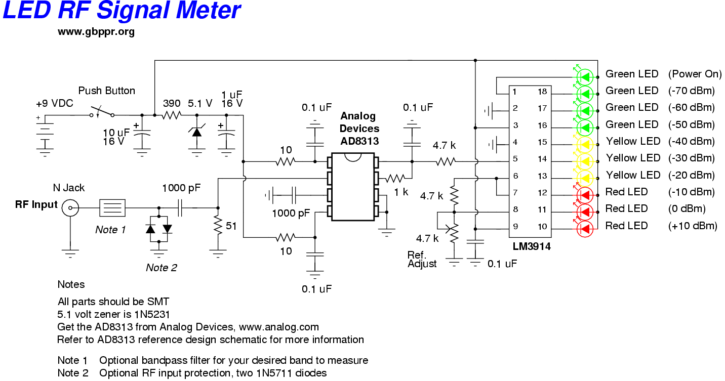
This RF Wave Absorption meter detects signals from 10 centimeters to 10 meters, depending on the setting of the 22 MegOhm gain adjustment potentiometer and the transmitter power. The RF signal is captured through germanium OA91 diodes and rectified...
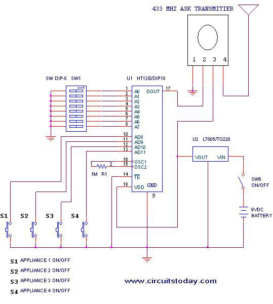
This project outlines a simple remote control system utilizing RF communication without the use of a microcontroller. The remote is designed for various home appliances such as televisions, fans, and lights, providing significant convenience by allowing operation from a...
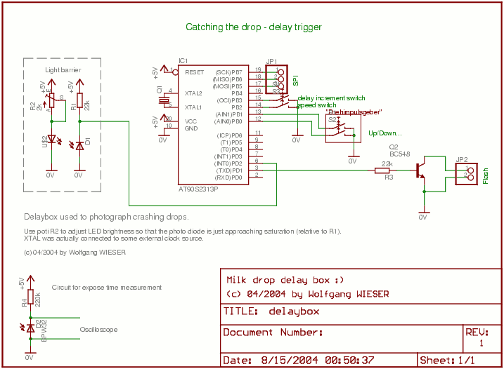
The objective is to capture images of a rapid process, which occurs too quickly for the human eye to perceive, at precisely specified intervals with sub-millisecond accuracy. While utilizing specialized equipment like a high-speed camera would simplify this task,...
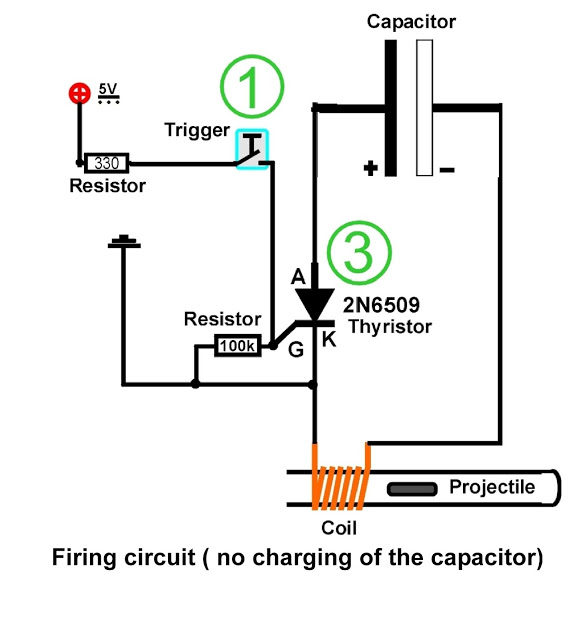
A coil is wound around a non-conductive tube, which serves as the barrel of the coilgun. The tube must be made from a non-conductive material, such as plastic, to prevent the coil's magnetic field from canceling itself out within...