
2 Siren Sound Use IC555 Schematic Diagram
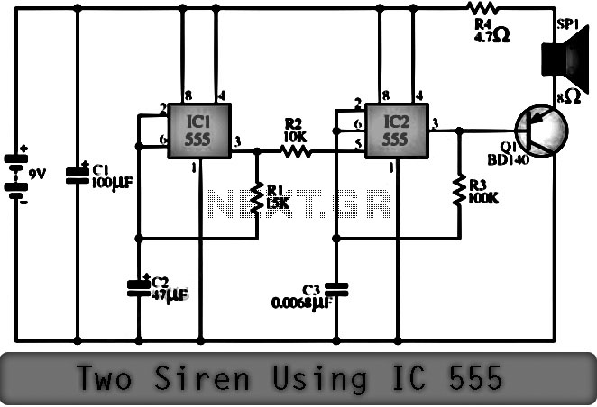
The Two Siren Sound Circuit employing the IC 555 integrates a low-frequency generator and a high-frequency oscillator to create distinct sound patterns. The circuit's architecture begins with IC1, configured as an astable multivibrator, which generates a low-frequency square wave output. The frequency of this output is influenced by the values of resistor R1 and capacitor C2, where their combinations dictate the oscillation rate. This low-frequency tone, approximately 1 Hz, is accessible from pin 3 of IC1 and is further conditioned through resistor R2.
The high-frequency component is produced by IC2, which receives input from the output of IC1 at pin 5. The setup of IC2 is crucial for generating a shrill sound, where the oscillation frequency is determined by resistors R3 and capacitor C3. The selection of C3 is particularly significant; a smaller capacitance results in a higher frequency output, thus producing a more treble-like sound. The output from pin 3 of IC2 is subsequently directed to the base of transistor Q1, which functions as an amplifier. This amplification is essential for driving speakers, ensuring that the generated sound is audible and impactful.
The overall circuit design allows for simultaneous low and high-frequency sound generation, creating a siren effect that can be utilized in various applications, such as alarms or signal devices. The careful selection of component values enables customization of the sound characteristics, making the circuit versatile for different use cases.Function of the Two Siren Sound Circuit that is using IC 555. Siren Circuit is separated into three parts: low frequency production. The manufacturing shrill frequency and annex of production low frequency is obtained from IC1 connected to astable multi vibrator circuit frequency is prearranged by R1, C2 frequencies with the purpose of are advent revealed of pin 3 is almost 1 Hz through R2 to subsist noble 5. of IC2, a division manufacture high-frequency input next to Pin 5 pray tone the origin of oscillator IC2 is the move of voltage from the output of IC1 frequency of IC2 is being set by R3, C3, which, if C3 help. will be alive very low tone if C3 is a lesser amount of treble The output preference suffer to podium out at home three legs of IC2 to stimulate B of Q1 to amplify signals to drive speakers.
You are reading the Circuits of 2 Siren Sound Use IC555 And this circuit permalink url it is 🔗 External reference
Related Circuits
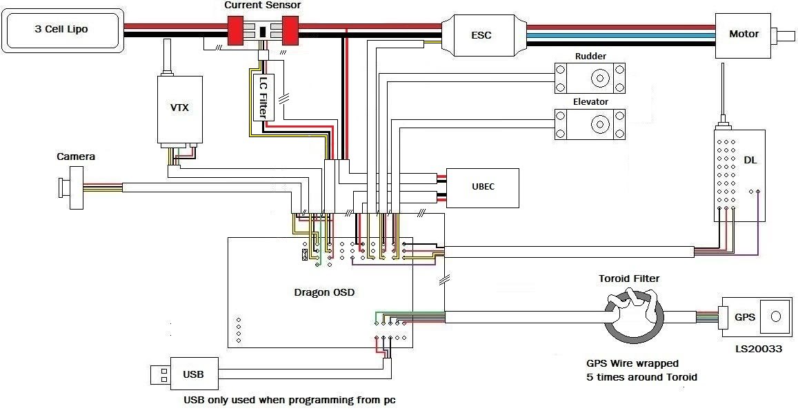
A discussion has been initiated regarding the diagrams being created. The initial set pertains to the DOSD (Dual OSD). Following the discovery of a potential issue, these new diagrams will facilitate safe wiring of the DOSD, thereby avoiding the...

Specializing in unique and hard-to-find CB radio books, plans, kits, modifications, repairs, technical information, and high-performance CB accessories since 1976. The focus on CB (Citizens Band) radio equipment encompasses a wide array of products and services tailored to enthusiasts and...
Grounding the blue wire at the headlamp switch causes the lights to illuminate, indicating a faulty switch. Continuity of the switch has already been verified. The relay consists of two small terminals and two larger ones. The smaller terminal,...

The circuit operates based on the principle that neon tubes N1, N2, and the photosensitive resistor RG1 form an optocoupler. When a finger touches the metal sheet S1, N1 lights up, causing RG1's resistance to decrease. This reduction allows...

Life in the 21st century would be nearly unbearable without some of the computer peripherals that PC users now consider essential. For instance, the USB-powered teacup warmer is an invaluable productivity tool for all users; however, it may draw...
Most 24V power systems in trucks, 4WDs, RVs, boats, and similar applications utilize two series-connected 12V lead-acid batteries. The charging system is capable of maintaining the total voltage of the individual batteries. If one battery is experiencing failure, this...