
FPV wiring Diagrams
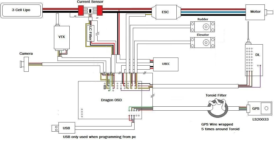
The DOSD (Dual On-Screen Display) is a critical component for various electronic applications, particularly in remote-controlled (RC) aircraft systems. This device provides real-time telemetry data, enhancing situational awareness for the operator. The newly developed wiring diagrams are designed to address a previously noted concern regarding incorrect connections that could lead to malfunction or damage.
The diagrams include a detailed pinout configuration, specifying the connections for power supply, signal input, and output lines. Each connection point is clearly labeled, ensuring that users can follow the schematic without confusion. It is recommended to use color-coded wires to correspond with the diagram for easier identification during assembly.
In the context of the Easystar Basic Specification, the DOSD can be integrated with the flight controller to display essential flight data such as altitude, speed, and battery voltage. The schematic outlines the necessary components, including resistors, capacitors, and connectors, which are essential for ensuring stable operation.
The power supply circuit is particularly emphasized, as it must be capable of supplying adequate voltage and current to both the DOSD and the connected sensors. Proper filtering is also indicated to prevent noise from affecting the performance of the telemetry data.
In conclusion, the provided diagrams not only simplify the installation process but also enhance the reliability of the DOSD in various applications, ensuring that users can operate their systems safely and effectively. The inclusion of full-size images aids in visualizing the assembly process, making it accessible for both novice and experienced users.Hi lads, I thought I`d start a thread on the diagrams I`m making. This first set is for DOSD. After a potential problem was discovered recently these new diagrams will enable you to wire up the DOSD perfectly safely avoiding the potential problem. Click on attachments for full size pictures Ok first the most common application : Easystar Basic Spec :..
🔗 External reference
Related Circuits
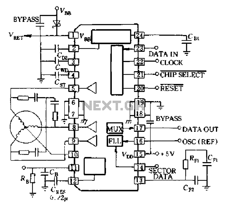
A8902 is a typical application wiring diagram. After a system failure signal from the delay island and CB 11 feeds into the motor brake, the system stops functioning until the RESET signal arrives, at which point the motor restarts. The...
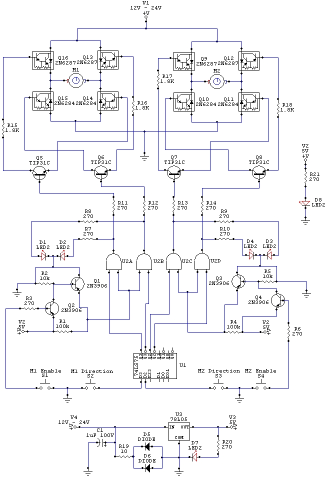
The wiring schematic played a significant role in the robot. This diagram is used to graphically display all the wiring of the motor-controlling micro-components that enabled the robot to physically move forward, backward, left, right, and stop. This diagram...
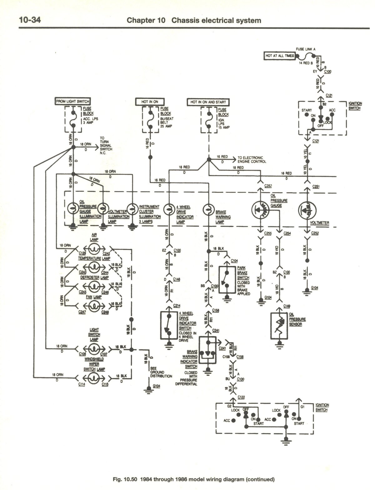
If there is no output at terminal 66 RED, it indicates a potential issue. The dash light dimmer may be set to the "OFF" position, or there could be significant corrosion on the wiper of the rheostat, preventing proper...
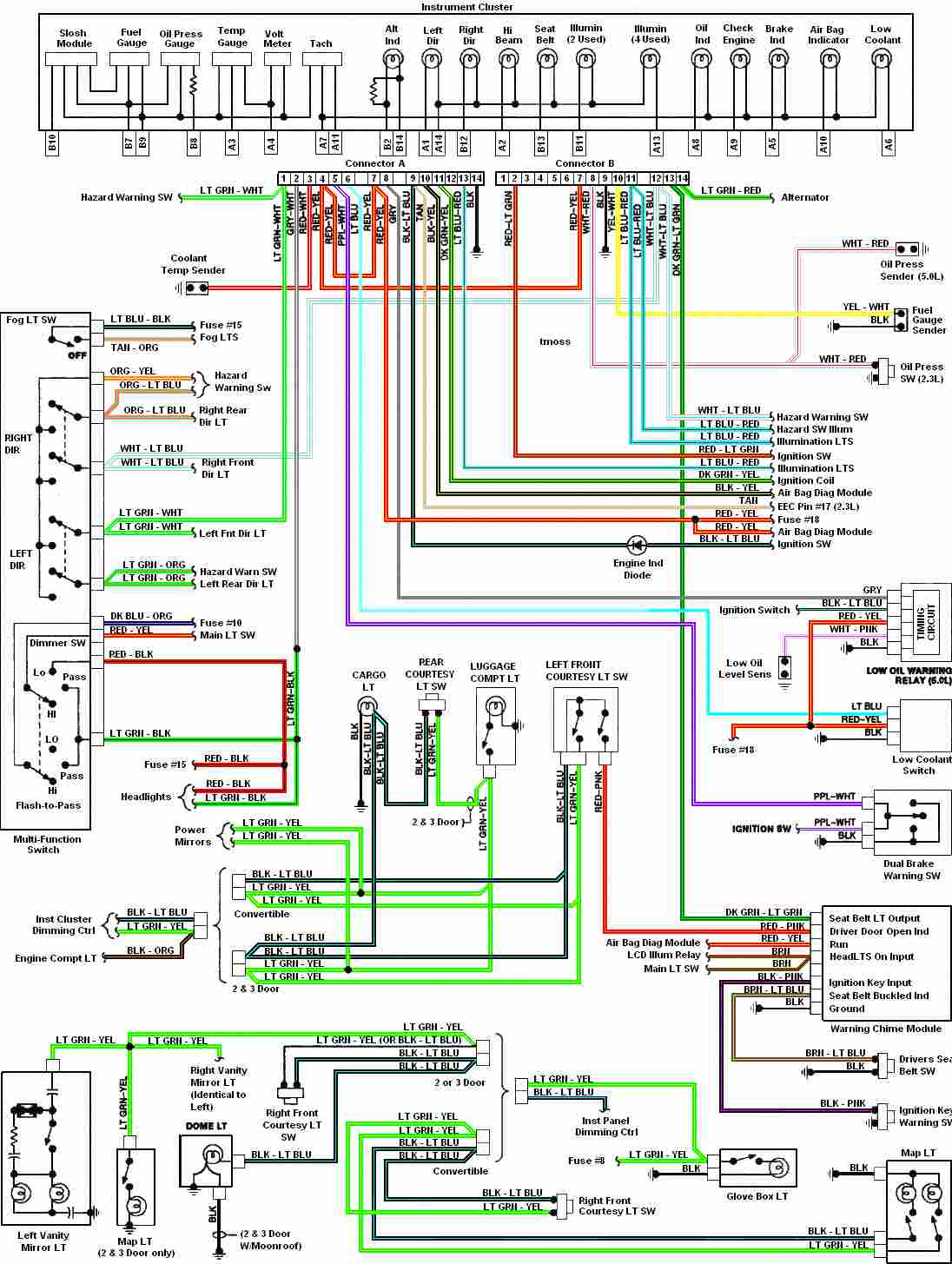
Automotive diagram for the instrument cluster of the 1987-1993 Ford Mustang (Third Generation). The instrument cluster for the 1987-1993 Ford Mustang serves as a critical interface for the driver, providing essential information about the vehicle's operational status. This cluster typically...
The two unspecified polarized capacitors (one directly above the transformer and one directly to the right of the transformer) are actually each a pair of 470 µF capacitors in parallel (for a total of four 470 µF capacitors). These...
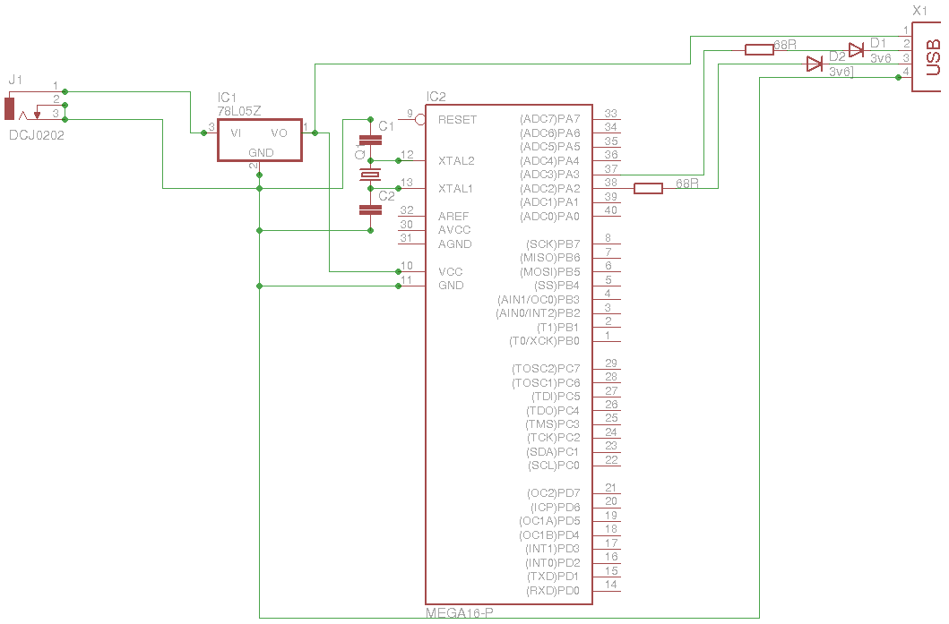
The 5 V from USB appears to be powering the LED on the laptop power brick. Therefore, even when the power brick is turned off at the wall outlet, the LED remains illuminated. When the USB is unplugged, the...