
USB Fuse
The MAX1562 USB current limiter is designed to protect both the USB device and the host system from excessive current draw that could lead to component failure. The integration of a charge pump for gate biasing ensures that the MOSFET operates efficiently, allowing for rapid response to changes in load conditions. The ability to distinguish between overload and short circuit conditions is critical for maintaining device integrity, and the pulsing output current method provides a means to recover from temporary faults without immediate shutdown, which is advantageous in applications with high inrush currents.
The adjustable current limit feature allows designers to tailor the device to specific application requirements, enhancing flexibility in design. The thermal cutoff adds an additional layer of protection, ensuring that the device remains operational within safe temperature limits. The integration of an LED indicator for FAULT conditions provides a visual cue for troubleshooting, making it easier to identify and rectify issues during operation.
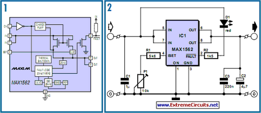
The compact 8-pin SMD package facilitates easy integration into space-constrained designs, while the PCB layout considerations ensure optimal performance with minimal parasitic effects. The use of SMD components not only saves board space but also enhances the overall reliability of the circuit by reducing the number of solder joints and potential failure points. Overall, the MAX1562 represents a robust solution for managing USB power delivery in a variety of applications, from consumer electronics to industrial systems.Life in the 21st century would be almost unbearable without some of the computer peripherals that PC users now look on as essentials - take for example the USB powered teacup warmer; this device is obviously an invaluable productivity tool for all users but it could prove a little tire some if the extra current it draws from the USB port is suffic ient to produce a localised meltdown on the motherboard. In a slightly more serious vein a similar situation could result from a carelessly wired connector in the design lab during prototyping and development of a USB ported peripheral. What`s needed here is some form of current limiting or fuse to prevent damage to the motherboard. The MAX1562 shown in Figure 1 is a purpose-built USB current limiter from the chip manufacturers Maxim.
The device operates with a supply voltage from 4. 0 to 5. 5 V with an operating current of typically 40 A or 3 A in standby mode. The circuit introduces a very low resistance in the power line (typically 26 m but guaranteed less than 50 m) from an internal MOSFET. The FET gate bias voltage is generated on-chip from a charge pump circuit. The chip can distinguish between an overload and a short circuit condition in the supply line by measuring the voltage drop across its internal resistance; if the voltage is less than 1 V a short circuit is assumed and the chip pulses a (limited) output current every 20 ms in an effort to raise the output voltage.
This approach will eventually be successful if the short circuit was caused by a large value capacitor across the USB supply pins or an external hard drive which have a high in-rush at start up. If the supply rail is not pulled up within the first 20 ms the FAULT output (pin 2) is driven low. The output current limit is set by a single resistor on pin 4 (ISET): LIM = 17120 / RSET. The circuit diagram shows a fixed 5. 6k resistor in series with a 10k preset giving an adjustable current limit between 1. 097 and 3. 057 A. This range should be sufficient for the majority of applications. Increasing the preset resistance reduces the current limit level. Any intermittent connection in the preset (caused by a dirty track etc. ) will switch the chip into shut down. The MAX1562 also contains a thermal cut out which turns off the output when the chip temperature exceeds 160 degrees C.
Figure 2 shows a diagram of the manufacturer`s application circuit. The FAULT output drives an LED via a series limiting resistor which reduces the LED current to 2 to 3 mA. The MAX1562 is available in a HESA variant (with an active high ON signal) or ESA version (with an active low ON signal).
The chip is packaged in an 8-pin SMD outline. Figure 3 shows a small PCB layout for the circuit using mostly SMD components. 🔗 External reference
Related Circuits
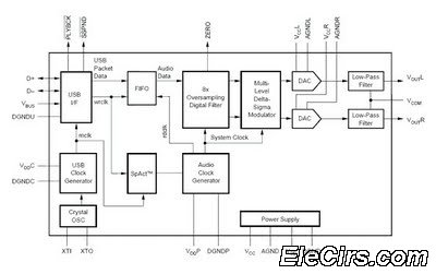
The USB sound card circuit utilizes the PCM2702 integrated circuit (IC) to create a fully functional USB sound card. The design is straightforward, allowing for the easy implementation of audio processing capabilities. The PCM2702 is a versatile USB audio controller...
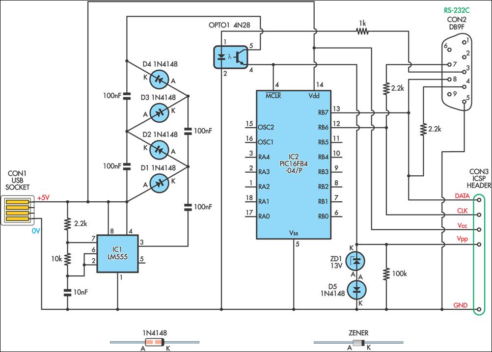
This simple circuit can be used to program the PIC16F84 and similar flash memory type components. It utilizes a 555 timer integrated circuit (IC) to generate the programming voltage from a +5V power supply, enabling operation from a computer's...
When the current through the load exceeds a level determined by the position of the wiper on the 1k wire-wound pot, this circuit cuts off the load immediately. If S1 is open, the range is approximately 300-650 mA, and...
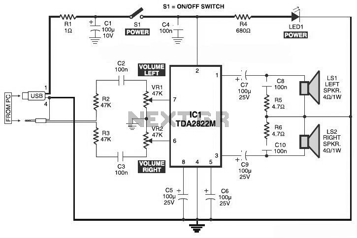
This is the circuit diagram of a USB-powered computer speaker, commonly known as multimedia speakers for PCs. The circuit features a single-chip design, operates on a low-voltage power supply, and is compatible with USB power from a computer. The USB-powered...

An N2PK Vector Network Analyzer (VNA) was utilized for antenna measurements, with an intention to operate it using a laptop PC. Due to the absence of parallel ports on most modern laptops, the exploration of running the VNA via...
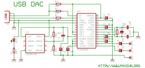
There is a significant interest in audio DAC design, particularly in creating a low-cost yet powerful audio DAC. This guide will provide instructions on how to build a personal audio DAC using the PCM2902 circuit. The project involves designing...