
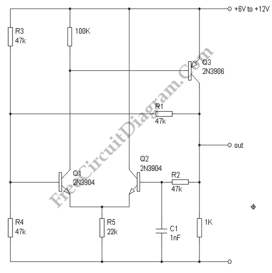
20 kHz Astable Multivibrator with Transistors
An astable multivibrator is a fundamental electronic circuit that generates a continuous square wave output without requiring any external triggering. The circuit consists of two unstable states, oscillating between them, which results in a periodic output signal. The primary components involved in the design of an astable multivibrator include resistors, capacitors, and active devices such as operational amplifiers or transistors.
In the case of a transistor-based astable multivibrator, two NPN transistors can be configured in a feedback loop. The timing of the oscillation is determined by the values of the resistors and capacitors connected to the transistors. When the circuit is powered, one transistor turns on, causing the other to turn off, and vice versa. This switching action creates a square wave output at the collector of one of the transistors.
For an op-amp astable multivibrator, the configuration typically involves connecting the op-amp in a feedback loop with resistors and capacitors. The output oscillation frequency can be adjusted by changing the resistor and capacitor values, allowing for flexibility in design based on application requirements.
The output frequency (f) of the astable multivibrator can be calculated using the formula:
f = 1 / (ln(2) * (R1 + 2R2) * C)
where R1 and R2 are the resistances in ohms, and C is the capacitance in farads. This equation highlights the relationship between the timing components and the frequency of the output signal.
Astable multivibrators are widely used in various applications, including clock pulse generation, LED flashers, and tone generation in audio devices. The simplicity and versatility of the astable multivibrator make it a fundamental building block in electronic circuit design.Astable multivibrator or oscillator circuit is based on positive feedback. We can design such circuit using op-amp, logic gates, or transistors. Here we can. 🔗 External reference
Related Circuits
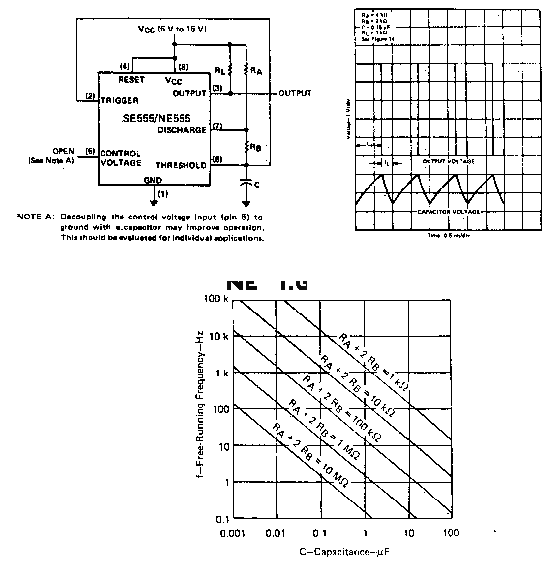
The capacitor C will charge through resistors Ra and Rb, and then discharge through resistor Rb only. The duty cycle may be controlled by the values of Ra and Rb. In this circuit configuration, a capacitor (C) is utilized to...
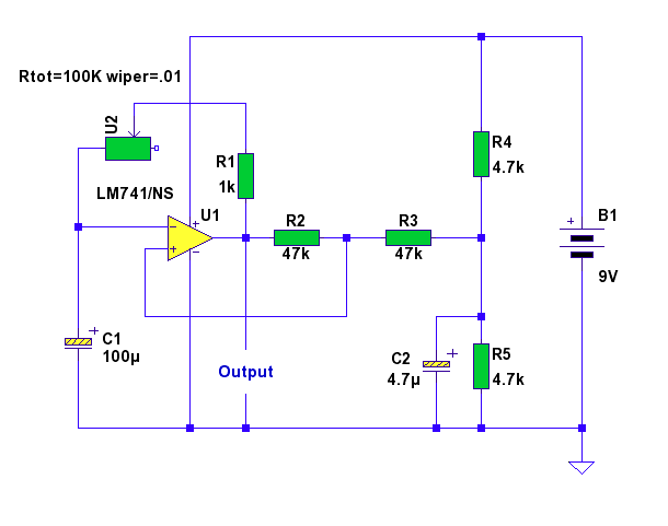
In this circuit, a standard operational amplifier (op-amp) is configured as an astable multivibrator. The output is non-symmetrical, but it has the advantage of being controlled by only one resistor and one capacitor: a 100k variable resistor (U2) and...
The power supply varies, and the circuit must operate at under 10 µA of current (excluding the capacitor charging). It triggers a Silicon Controlled Rectifier (SCR) every 10 to 30 seconds as long as the power supply is above...
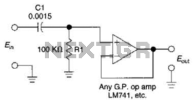
This simple 1 kHz filter utilizes a voltage follower and an RC section as its filtering element. For other frequencies, the -3 dB point is given by the formula 1/(6.28 Rl Cv), and the response decreases at a rate...
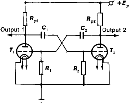
A relaxation oscillator utilizes two tubes, transistors, or other electronic devices, with the output of each connected to the input of the other through resistance-capacitance elements or other components to achieve in-phase feedback voltage. This electronic circuit employs positive...

This circuit design generates a stable 1 kHz sine wave using an inverted Wien bridge configuration with components C1-R3 and C2-R4. It offers a variable output, low distortion, and low output impedance to ensure good overload capability. The circuit...