
Multivibrator

The described relaxation oscillator circuit can be utilized in various applications, including timers, frequency generators, and pulse-width modulation systems. The bistable multivibrator configuration allows for stable data storage and switching applications, making it suitable for digital memory elements. The monostable multivibrator can serve as a timing element, producing single output pulses of predetermined duration in response to triggering events. The astable multivibrator configuration is particularly useful for generating continuous square wave signals, which can be employed in clock generation for digital circuits.
In practical implementations, the choice of transistors or tubes affects the performance characteristics of the oscillator, including frequency stability, power consumption, and output signal integrity. Designers must carefully select component values for the resistors and capacitors in the feedback network to achieve the desired frequency and duty cycle for the output waveform. Additionally, the layout of the circuit on a printed circuit board (PCB) can influence the overall performance, with attention paid to minimizing parasitic capacitance and inductance.
Overall, the relaxation oscillator serves as a fundamental building block in electronic design, illustrating the principles of feedback and state control in circuit operation.A relaxation oscillator using two tubes, transistors, or other electron devices, with the output of each coupled to the input of the other through resistance-capacitance elements or other elements to obtain in-phase feedback voltage. A form of electronic circuit that employs positive feedback to cross-couple two devices so that two distinct states
are possible, for example, one device ON and the other device OFF, and in which the states of the two devices can be interchanged either by use of external pulses or by internal capacitance coupling. When the circuit is switched between states, transition times are normally very short compared to the ON and OFF periods.
Hence, the output waveforms are essentially rectangular in form. Multivibrators may be classified as bistable, monostable, or astable. A bistable multivibrator, often referred to as a flip-flop, has two possible stable states, each with one device ON and the other OFF, and the states of the two devices can be interchanged only by the application of external pulses. A monostable multivibrator, sometimes referred to as a one-shot, also has two possible states, only one of which is stable.
If it is forced to the opposite state by an externally applied trigger, it will recover to the stable state in a period of time usually controlled by a resistance-capacitance (RC) coupling circuit. An astable multivibrator has two possible states, neither of which is stable, and switches between the two states, usually controlled by two RC coupling time constants.
The astable circuit is one form of relaxation oscillator, which generates recurrent waveforms at a controllable rate. In bistable multivibrators, either of the two devices in a completely symmetrical circuit may remain conducting, with the other nonconducting, until the application of an external pulse.
Such a multivibrator is said to have two stable states. The original form of bistable multivibrator made use of vacuum tubes and was known as the Eccles-Jordan circuit, after its inventors. It was also called a flip-flop or binary circuit because of the two alternating output voltage levels.
The junction field-effect transistor (JFET) circuit (Fig. 1) is a solid-state version of the Eccles-Jordan circuit. Its resistance networks between positive and negative supply voltages are such that, with no current flowing to the drain of the first JFET, the voltage at the gate of the second is slightly negative, zero, or limited to, at most, a slightly positive value. The resultant current in the drain circuit of the second JFET causes a voltage drop across the drain load resistor; this drop in turn lowers the voltage at the gate of the first JFET to a sufficiently negative value to continue to reduce the drain current to zero.
This condition of the first device OFF and the second ON will be maintained as long as the circuit remains undisturbed. See Transistor If a sharp negative pulse is applied to the gate of the ON transistor, its drain current decreases and its drain voltage rises.
A fraction of this rise is applied to the gate of the OFF transistor, causing some drain current to flow. The resultant drop in drain voltage, transferred to the gate of the ON transistor, causes a further rise at its drain.
The action is thus one of positive feedback, with nearly instantaneous transfer of conduction from one device to the other. There is one such reversal each time a pulse is applied to the gate of the ON transistor. Normally pulses are applied to both transistors simultaneously so that whichever device is ON will be turned off by the action.
The capacitances between the gate of one transistor and the drain of the other play no role other than to improve the high-frequency response of the voltage divider network by compensating for the input capacitances of the transistors and thereby improving the speed of transition. A bipolar transistor counterpart of the JFET bistable mu 🔗 External reference
Related Circuits
A transistorized astable multivibrator is a cross-coupled transistor network capable of generating a continuous square wave. It operates as a free-running oscillator or a regenerative switching circuit that utilizes positive feedback. The astable multivibrator continuously alternates between its two...
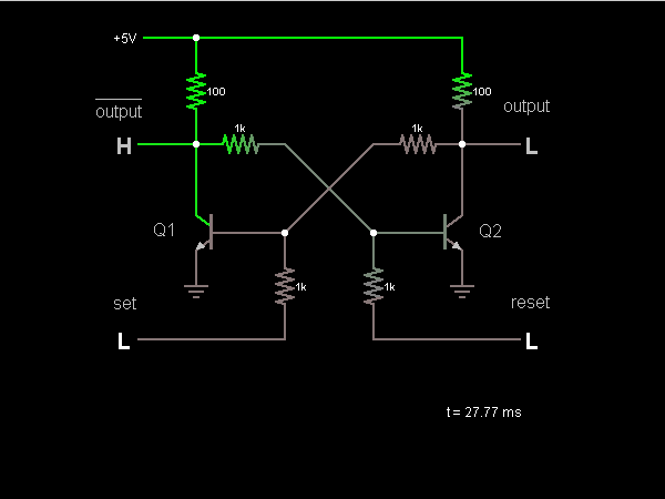
This circuit is a bistable multivibrator, commonly known as a flip-flop. Activating the "set" input located at the lower left corner will raise the output to a high state (5V). Conversely, engaging the "reset" input at the lower right...
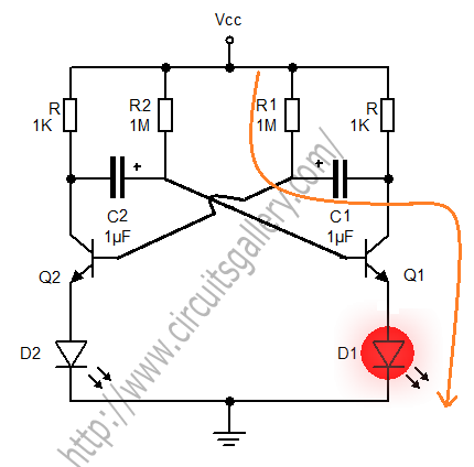
An astable multivibrator is a switching circuit that alternates its output on and off for a designated time period. This device, also known as a free-running oscillator circuit, is primarily utilized to generate square waves over a specified duration....
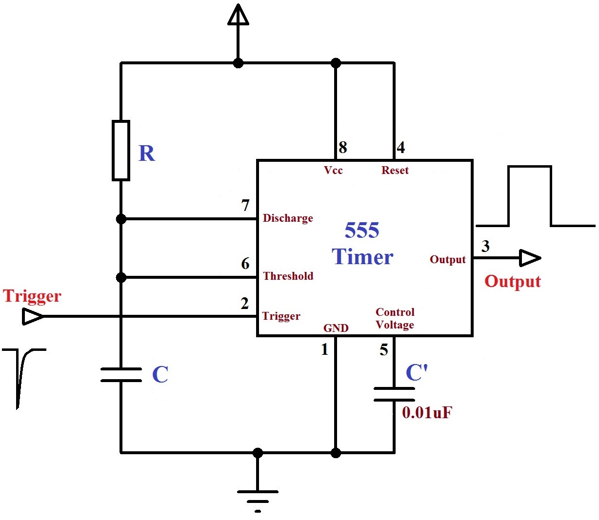
The monostable mode of the 555 Timer operates by having one stable state and switching to an unstable state for a predetermined time period T when triggered. The time period T is determined by the RC time constant in...
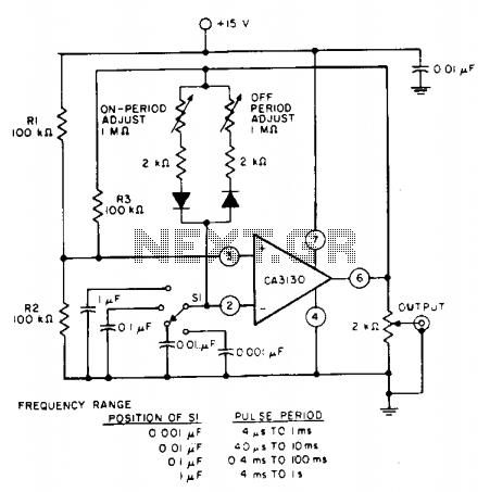
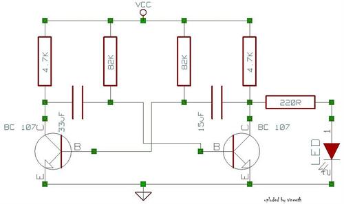
The pulse repetition rate is determined by adjusting switch SI to the desired position, and this rate remains relatively constant even when the resistors that control the on-period and off-period are modified. Resistors R1 and R2 set the biasing...
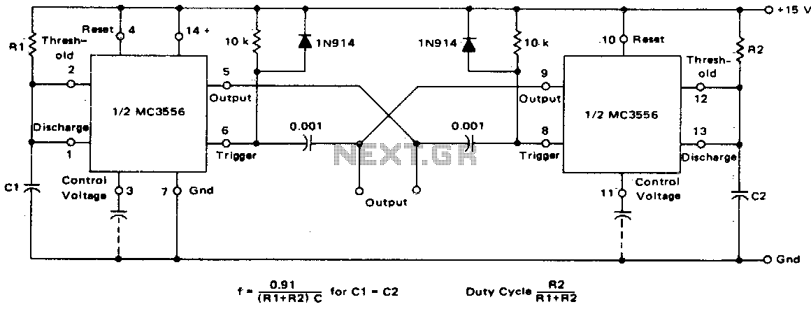
This dual astable multivibrator offers versatility not found in single timer circuits. The duty cycle can be adjusted from 5% to 95%. The two outputs generate two-phase clock signals, which are frequently required in digital systems. Additionally, it can...