
20 MHz VHF CRYSTAL OSCILLATOR
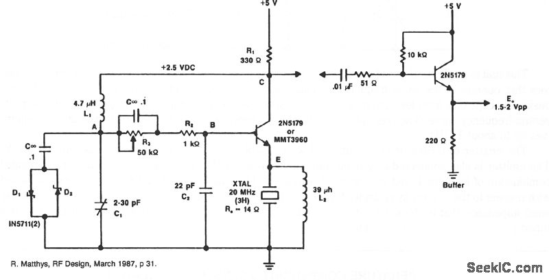
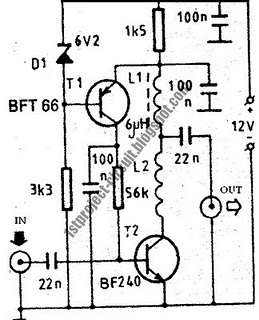
This circuit operates at a frequency of 20 MHz, utilizing a crystal oscillator that is tuned to its third harmonic. The crystal's internal series resistance (RS) of 14 ohms plays a critical role in determining the quality factor and stability of the oscillation. The harmonic oscillation allows for efficient signal generation, making it suitable for various applications in communication systems.
The inclusion of diode clamps D1 and D2 serves to regulate the amplitude of the oscillations, ensuring that the output signal remains within a defined voltage range. This is particularly important in preventing signal distortion and maintaining the integrity of the waveform during operation. These diodes work by clipping the peaks of the oscillation, thereby providing a form of amplitude stabilization.
The transistor in this circuit is designed to operate in a linear mode, allowing it to amplify the oscillating signal without introducing significant distortion. By maintaining a continuous operation throughout the oscillation cycle, the transistor helps to ensure that the load presented to the crystal remains relatively constant. This consistent load is crucial for sustaining the oscillation and achieving stable frequency output.
Overall, the circuit exemplifies the principles of harmonic oscillation, amplitude control, and linear amplification, making it a robust solution for frequency generation at 20 MHz. The careful selection of components, including the crystal, diodes, and transistor, is essential for optimizing performance and ensuring reliability in practical applications.A typical circuit at 20 MHz is shown. The crystal, which has an internal series resistance RS, of 14 ©, oscillates at its third harmonic. The diode clamp D1 and D2 provides a constant amplitude control. The transistor operates continuously in a linear mode over a complete cycle of oscillation, and reflects a reasonably constant load across the c rystal at an times. 🔗 External reference
Related Circuits
An idea proposed is to utilize a phase shift oscillator followed by an inverter to convert a sine wave into a square wave; however, this may be considered a rudimentary solution. There is also interest in schematics for a...
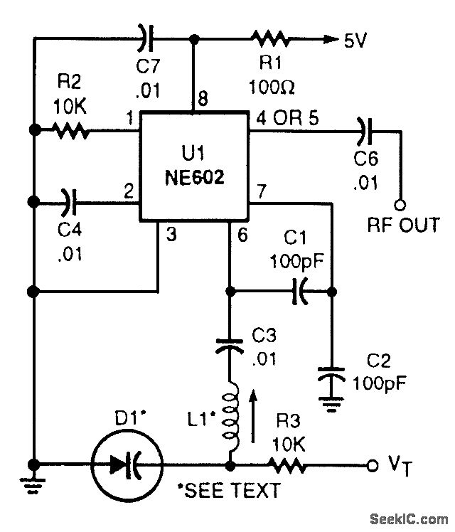
This voltage-tuned Clapp oscillator utilizes a varactor diode to determine its operating frequency. The diode used is an NTE614, and the inductor L1 has a value of approximately 7 microhenries. With this configuration, the oscillator can operate within a...
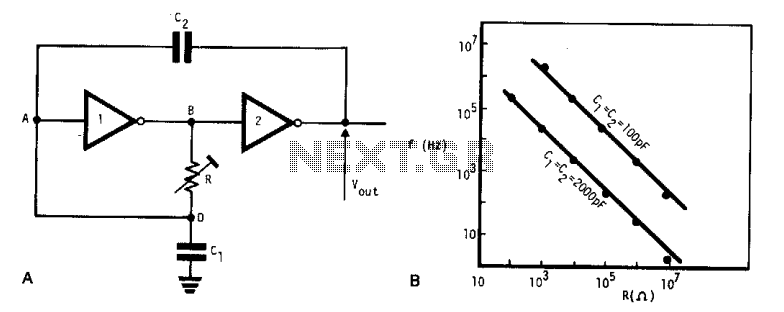
This simple, low-cost oscillator is constructed using two CMOS buffer inverters, two capacitors, and a variable resistor. The circuit operates with voltage levels ranging from 4 V to 18 V. When C1 equals C2, the frequency of oscillation is...
Many radio amateurs are interested in powering simple radio receivers using "free energy," which refers to energy obtained directly from the air via the receiver antenna. The circuits described can facilitate radio reception through a loudspeaker. However, questions remain...
This design presents a simple antenna amplifier electronic circuit project, which can be utilized based on the provided circuit diagram. The antenna amplifier operates effectively within a frequency range of 1 to 300 MHz. It is suitable for high...
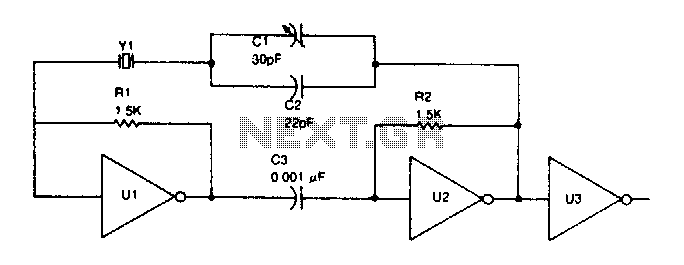
TTL inverter stages, U1 and U2, are cross-connected with a crystal Y1. A resistor in each stage biases the normally digital gates into a region where they operate as amplifiers. Inverter stage U3 is used as a buffer. The circuit...