
Micropower battery splitter
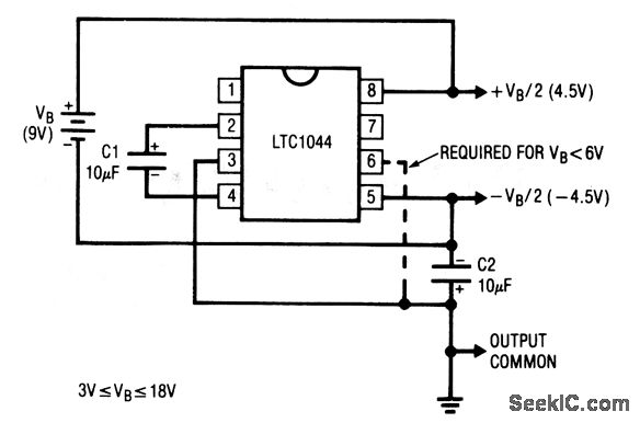
The described circuit functions as a voltage divider and inverter, producing dual output voltages that are symmetrical around a common reference point. The configuration typically involves operational amplifiers (op-amps) or a dedicated voltage inverter IC. The input voltage, which can be supplied by a single battery, is divided to create two output voltages: +Vout and -Vout, each at half the input voltage level.
In practical applications, when using a 9-V battery, the circuit generates +4.5 V and -4.5 V outputs. The reference point at pin 3 is crucial as it establishes a ground level for both output voltages, ensuring that the circuit can interface with other components effectively.
When the input voltage exceeds 6 V, the requirement to connect pin 6 to pin 3 ensures stability and proper operation of the circuit. This connection helps to maintain the integrity of the output voltages by providing a consistent reference point, preventing potential issues related to voltage fluctuations or unbalanced outputs.
The design can be implemented on a breadboard for prototyping or as a printed circuit board (PCB) for more permanent installations. Careful consideration should be given to the choice of components, including resistors and capacitors, to optimize performance and minimize noise in the output signals. Proper bypass capacitors should be employed near the power supply pins of the op-amps to ensure stable operation under varying load conditions.
Overall, this circuit is versatile and can be adapted for various applications requiring dual voltage supplies, such as powering analog sensors or operational amplifiers that require dual polarity supplies for signal processing.This circuit provides symmetrical ±output voltages, both equal to one-half the input voltage (one 9-V battery in this case). The output voltages are referenced to pin 3 (output common). The circuit will operate with other battery voltages. If the battery exceeds 6 V, pin 6 should also be connected to pin 3, as shown by the dashed line. 🔗 External reference
Related Circuits
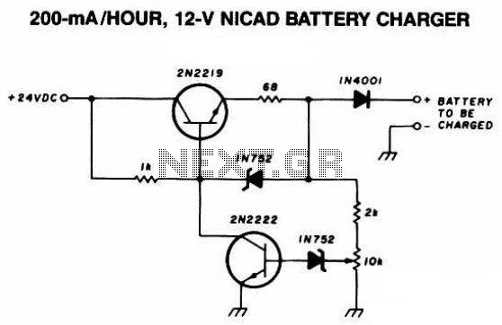
The following diagram is the schematic diagram of a 12V NiCAD battery charger with a charging rate of 200mA per hour. This NiCAD battery charger circuit charges the battery at 75 mA until the battery is fully charged, after...
While owning a modern NiCd battery charger, there may still be instances where an incompatible battery is encountered, such as one with a unique voltage requirement or one that necessitates a higher charging current than what a standard charger...
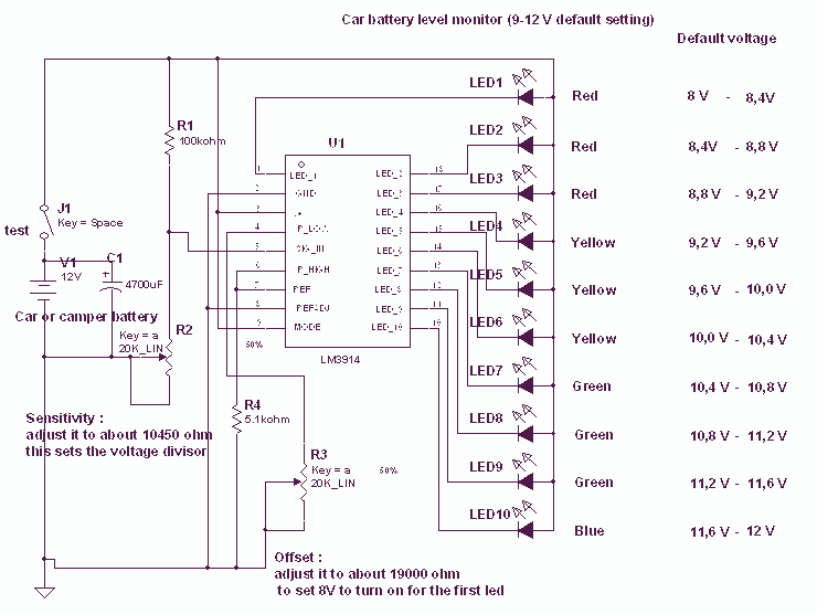
This circuit uses the popular and easy to find LM3914 IC. This IC is very simple to drive, needs no voltage regulators (it has a built-in voltage regulator) and can be powered from almost every source. When the test...
A power inverter converts direct current (DC) power to standard alternating current (AC) power. The following schematic illustrates a 12V power inverter circuit diagram. The 12V power inverter circuit typically consists of several key components that work together to achieve...
This circuit allows appliances to remain connected to an inverter. While it does not influence weather conditions, it ensures that batteries are safely charged even during periods of generation shortfall. This device is referred to as the Grid Charger...
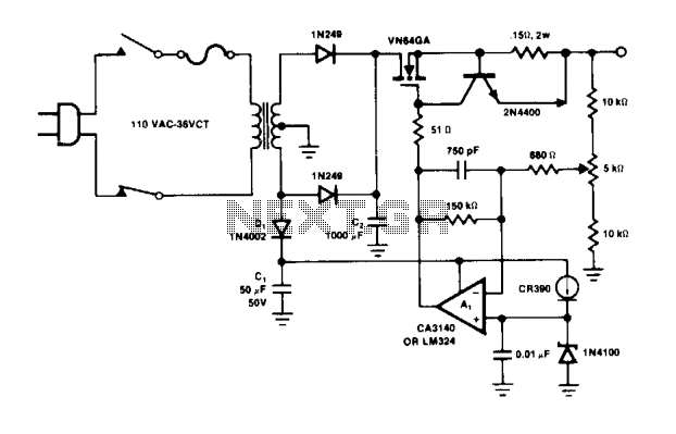
The operational amplifier A1 directly drives the VN64GA with the error signal to control the output voltage. The peak rectifier D1 and capacitor C1 supply the error amplifier A1 and the reference zener. This additional drive voltage must exceed...