
2006 Toyota 4Runner Electrical
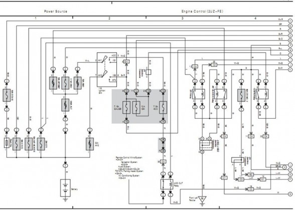
The electrical circuit diagram of the 2006 Toyota 4Runner serves as a comprehensive representation of the vehicle's electrical system. This schematic outlines various components such as the battery, alternator, fuses, relays, and wiring harnesses, providing a clear view of how these elements interact within the vehicle.
Key features of the circuit diagram include the layout of the power distribution system, which ensures that electrical energy is efficiently routed to different subsystems, including lighting, infotainment, and safety systems. The diagram also highlights the safety mechanisms integrated into the vehicle, such as airbag systems and anti-lock braking systems (ABS), showcasing how they are powered and controlled.
Additionally, the circuit diagram provides vital information regarding the specifications of the vehicle's electrical components, including voltage ratings, current capacities, and resistance values. This information is essential for troubleshooting electrical issues, performing maintenance, or making modifications to the vehicle's electrical system.
Overall, the electrical circuit diagram for the 2006 Toyota 4Runner is an indispensable tool for automotive technicians and engineers, facilitating a thorough understanding of the vehicle's electrical architecture and ensuring safe and efficient operation.The following circuit shows about 2006 Toyota 4Runner Electrical Circuit Diagram. Features: specs on Toyota car, and how the use of safety for .. 🔗 External reference
Related Circuits
A Transcutaneous Electrical Nerve Stimulation (TENS) device is essentially a machine that delivers electric shocks. This device was prescribed on a loan basis by an orthopedic specialist. The unit features numerous programs, although only one was utilized. Measurement of...
Electrical lines that include lighting circuits originate from the main distribution panel of the installation. Each line consists of three conductors: phase, neutral, and ground. All three conductors extend to the terminal point of each luminaire, and if the...
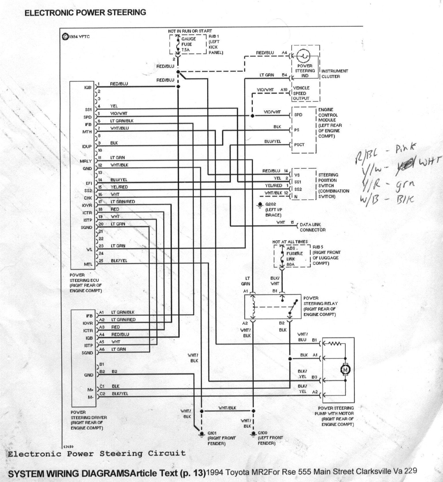
The goal was to control the MR2 power steering pump to reduce noise and power consumption, as it operates at full throttle continuously. Designing a custom motor controller was not feasible due to a lack of expertise, and off-the-shelf...
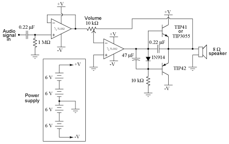
It is advisable to obtain TIP41 and TIP42 transistors, which are closely matched NPN and PNP power transistors with dissipation ratings of 65 watts each. If a TIP41 NPN transistor is unavailable, the TIP3055 (available from Radio Shack) serves...
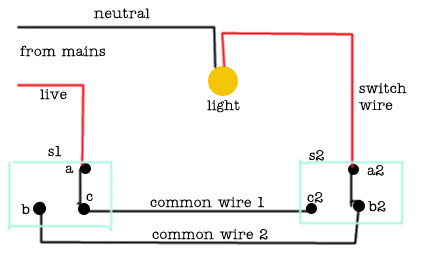
The following circuit illustrates a 2-way switch wiring electrical circuit diagram. Features include the ability to turn on the lights using switch S1, which has three terminals. The 2-way switch circuit is commonly used in residential and commercial applications to...
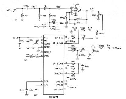
The objective of this project is to develop a multi-effect guitar processor capable of altering the tonal characteristics of a guitar. This device aims to provide a wide range of unique sounds, enhancing the entertainment value for users. The...