
Transcutaneous Electrical Nerve Stimulator (TENS)
The TENS device operates on the principle of delivering controlled electrical impulses to stimulate nerves, which can help alleviate pain by interrupting pain signals sent to the brain. The core of the circuit consists of a CMOS 555 timer configured in astable mode, generating a square wave output. The frequency of the output can be fine-tuned by adjusting the resistors and capacitors in the timing circuit, allowing for customization based on therapeutic needs.
The miniature transformer plays a critical role in stepping up the voltage of the output signal. The 1:10 ratio indicates that for every 1 volt input to the transformer, 10 volts will be output. This voltage amplification is crucial for the effectiveness of the TENS therapy, as higher voltages can penetrate deeper tissues and stimulate larger nerve fibers.
The resonant circuit formed by the transformer and the capacitor enhances the output voltage further, allowing for a more effective treatment. The choice of a 4.7 nF capacitor is based on its ability to resonate at the desired frequency, working in tandem with the inductance of the transformer to create a peak voltage output.
Safety is paramount in the design of the TENS device, particularly given the potential for high voltages. The selection of a transformer with appropriate insulation ratings ensures that the device operates safely without risk of electrical shock to the user. The use of a phono socket for the electrode connection provides a secure and easily replaceable interface for the electrodes, which are essential for delivering the electrical impulses to the skin.
The electrodes themselves must be carefully chosen based on their compatibility with the device and their intended use. The availability of both disposable and permanent types allows users to select based on comfort and hygiene preferences. The design of the electrode connectors to fit standard 2 mm banana plugs facilitates easy assembly and replacement of cables.
In conclusion, this TENS device design allows for effective pain management through electrical stimulation, with adjustable parameters to cater to individual needs. The circuit's simplicity enables DIY enthusiasts to replicate the device, while adhering to safety standards ensures its practical application in therapeutic settings.A Transcutaneous Electrical Nerve Stimulation (TENS) device is, put bluntly, a machine for giving electric shocks. The author was prescribed such a device on loan by his orthopaedic specialist. The unit has a large number of programmes, of which he used only one. Measuring the signals at the output of the device in this mode revealed damped oscill ations at a frequency of approximately 2. 5 kHz, with a repetition rate of approximately 100 Hz. How hard can it be to make such a device ourselves The simple circuit uses a CMOS 555 timer to produce a brief pulse which feeds a 1:10 miniature transformer. Together with a 4. 7 nF capacitor the transformer makes a parallel resonant circuit: the resonance leads to a considerable increase in the output voltage.
The pulse width can be adjusted using a potentiometer, here shown combined with the on-off switch. Wider pulses produce higher output voltages. Since a peak voltage of up to 200 V can be produced, the transformer must have adequate insulation: Conrad Electronics type 516260-62 is suitable. A low-cost phono socket at the output gives reliable connection to the electrode cable. The adhesive electrodes shown in the photograph (disposable and permanent types are available) can be obtained from pharmacies and medical suppliers.
They generally have connectors compatible with 2 mm banana plugs, and so it is possible to make up the necessary cable yourself. To treat responsive parts of the body, such as the arm, the potentiometer need not be turned up far to obtain the necessary sensation.
Less sensitive parts, such as the knee or foot, need a rather higher voltage and hence a correspondingly higher potentiometer setting. 🔗 External reference
Related Circuits
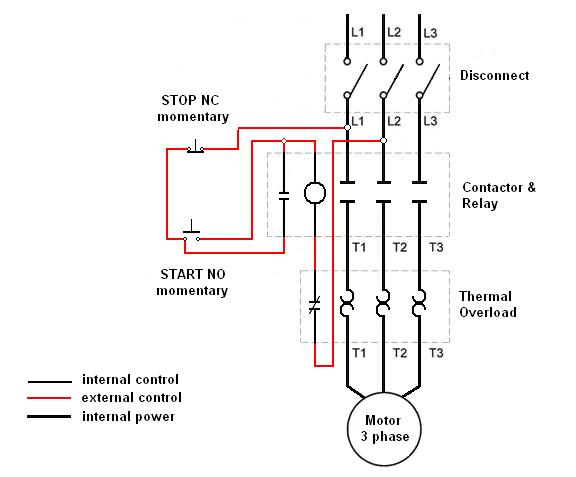
Wiring a three-phase motor through a two-pole vacuum switch involves two lines passing through the switch while one line remains continuously energized to the motor. Is this configuration correct, or does it present a safety concern? When wiring a three-phase...
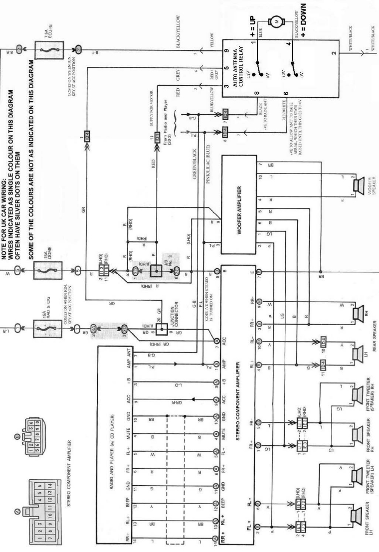
The following circuit illustrates an electrical circuit diagram for the MR2 MKII electric aerial. Features include control by an Aerial Control Relay, which consists of... The MR2 MKII electric aerial circuit is designed to facilitate the automatic operation of the...
The following document contains information related to the electrical installation schematic diagram for the Volvo 440. It includes the wiring schematic for the Volvo 440, 460, and 480 series. The Volvo 440, 460, and 480 series vehicles feature a comprehensive...
This is an electronic muscle stimulator circuit that stimulates the nerves in the area of the body where electrodes are attached. It is useful for relieving pain. The electronic muscle stimulator circuit operates by delivering electrical impulses through electrodes placed...
Note that the due dates for lectures 20-25 will be rescheduled to Wednesday at 1:00 PM. Download the notes for Topic 1: Basic Components (Listen to Dr. Stienecker) and Topic 2: Power and Connections (Listen to Dr. Stieneker). Students...
SW1 should be connected to P1 to prevent sudden voltage spikes on the patient's body during switch-on. However, a standalone SPST switch can also be effective, as long as the P1 knob is set fully counter-clockwise upon activation. Some...