
automatic water tank filler circuit diagram

The electronic schematic for this water level control circuit incorporates several key components and configurations to ensure reliable operation. The two water level sensors, typically constructed from stainless steel screws, serve as conductive probes that detect the presence or absence of water. These sensors are strategically positioned within the tank to define the upper and lower water levels. The lower sensor activates the pump when the water level drops below a certain threshold, while the upper sensor deactivates the pump once the water level reaches the desired maximum.
The use of Darlington transistors Q1, Q2, Q3, and Q4 enhances the circuit's ability to amplify the signals from the water sensors, enabling the NOR gate to produce a consistent output. The NOR gate configuration is crucial, as it ensures that the relay remains activated only when both sensors are not submerged, thereby preventing unintended activation of the pump.
Relay RLY1 controls the power supply to the pump, while solid-state relay RLY2 manages the high starting current required by the 3HP submersible bore pump. This arrangement allows for efficient control of the pump's operation without risking damage to the components due to excessive current.
The entire circuit is designed to operate within the harsh environmental conditions typically found on a farm, with the use of silicone sealant providing protection against moisture and corrosion at the wiring junctions. This design ensures that the livestock always have access to water, mitigating the risks associated with dehydration or flooding, thereby enhancing farm productivity and animal welfare.This circuit has been very useful in filling a header tank for a reticulated water supply on a farm. Eight troughs are supplied in different paddocks where a lack of water would have serious consequences for the stock. In the past, the tank had been filled daily by a time clock which was not successful. During hot weather, the stock would empty th e tank on a regular basis and then be without water for several hours or the tank would overflow and flood the area if the weather was wet and the cattle did not drink much. The circuit described has been used to maintain the level of water in the header tank within prescribed limits.
It controls a 3HP submersible bore pump which has a high starting current, necessitating a solid-state relay sufficient to take the starting load. Two Darlington transistors, Q1 & Q3, in conjunction with Q2 & Q4, are connected to the upper and lower water sensors in the tank.
Q2 & Q4 have a common 5. 6kO load resistor and function as a NOR gate. The output of the NOR gate drives Q5 which activates relay RLY1. Initially, when the water level is low, both sensors will be open-circuit, the NOR gate output will be high and the relay will be turned on. This causes the normally closed (NC) contacts of the relay to open and disconnect the lower sensor. However, the upper sensor will still be open circuit and the NOR gate output will be high, keeping the relay closed.
The normally open (NO) contact of the relay will be closed to operate the solid-state relay RLY2 to run the pump. This state continues until the water reaches the top sensor which will then drop the output from the NOR gate to 0V.
The disables relay RLY1 and the pump is stopped. In practice the upper level sensor is just below the overflow from the tank and the lower sensor about half way up the tank. The sensor contacts are simply two stainless steel screws about 25mm apart and screwed through the poly tank walls.
The wiring junctions on the side of the tank are protected by neutral-cure silicone sealant. 🔗 External reference
Related Circuits
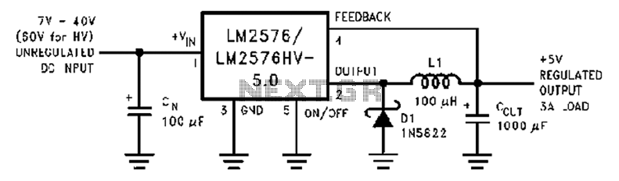
A wide range of 7 to 40V DC-DC step-down circuit that converts input voltage to 5V. This circuit operates as a buck converter, designed to efficiently reduce a higher DC voltage (ranging from 7V to 40V) to a stable output...
This FM transmitter circuit employs four radio frequency stages: a VHF oscillator built around the transistor BF494 (T1), a preamplifier constructed with the transistor BF200 (T2), a driver using the transistor 2N2219 (T3), and a power amplifier based on...
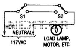
This switching arrangement is utilized in both domestic and industrial environments to enable control of a light or other AC-operated device from multiple locations. This switching arrangement, commonly referred to as a multi-way switching system, is designed to facilitate the...
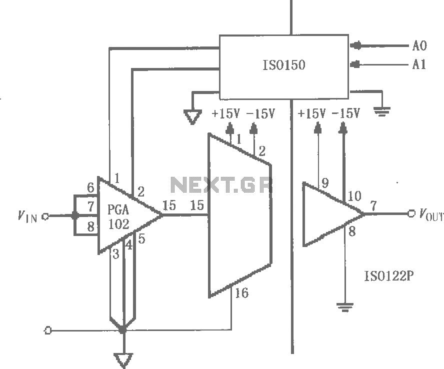
The circuit features grounds ISO122/124 and PGA102, with ISO150 forming a gain programmable channel isolation circuit. The input signal VIN is amplified by the instrumentation amplifier PGA102 to ISO122P, which then outputs VOUT from the isolation amplifier ISO102P. Two...
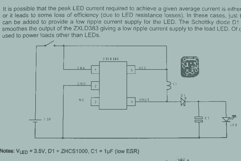
It may seem that due to the numerous flashlight projects undertaken, there is a significant collection of lights. The inductor can be altered to set the current level, but the total current fluctuates with the battery supply, decreasing as...
The State Jal Boards supply water for a limited duration each day. The timing of the water supply is determined by management, leaving the public unaware of the schedule. In this context, a water alarm circuit can alleviate long...