
19v dc regulation circuit diagram
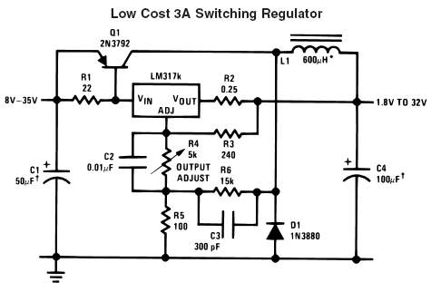
To convert a 24V DC supply to a different voltage level, several circuit configurations can be employed depending on the desired output voltage and current requirements. A commonly used method for this purpose is the DC-DC buck converter, which steps down the voltage efficiently.
The basic structure of a buck converter includes an inductor, a switch (typically a MOSFET), a diode, and a capacitor. The operation begins when the switch is closed, allowing current to flow through the inductor, which stores energy in the form of a magnetic field. When the switch opens, the inductor releases its stored energy to the load through the diode, while the capacitor smooths the output voltage.
For a 24V DC input, the buck converter can be designed to output various lower voltage levels, such as 12V, 5V, or even lower, depending on the duty cycle of the switching signal. The duty cycle is the ratio of the time the switch is on to the total time period of the switching cycle and can be adjusted using a pulse-width modulation (PWM) signal.
The components required for this circuit include:
1. A suitable MOSFET rated for the input voltage and load current.
2. An inductor with an appropriate inductance value to handle the desired current without saturating.
3. A Schottky diode to ensure minimal forward voltage drop and fast switching.
4. Output and input capacitors to filter voltage spikes and smooth the output.
5. A control IC or PWM generator to manage the switching frequency and duty cycle.
The circuit should also include protection features such as overcurrent protection, thermal shutdown, and input/output voltage regulation to ensure reliable operation under varying load conditions.
In summary, a buck converter is an effective solution for converting a 24V DC input to a lower voltage, with the design tailored to specific application requirements. Proper component selection and circuit design are crucial for achieving high efficiency and stable performance.thanks for your replies in my previous thread posted, i really appreciate. pls., how do i, and what circuit diagram should i use to convert a 24v dc.. 🔗 External reference
Related Circuits
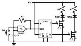
This project involves constructing a coin toss circuit that comprises three main sections: a square-wave oscillator, a JK flip-flop, and two LEDs (one red and one green). The circuit utilizes CMOS digital integrated circuits (ICs) and MOSFET transistors. The...
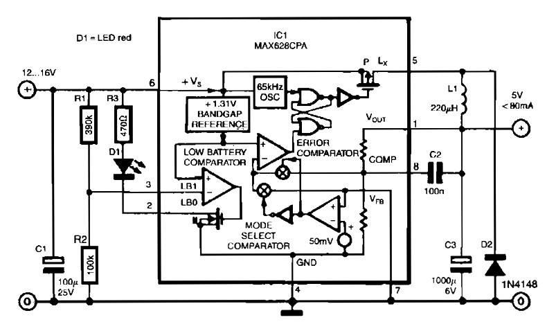
The circuit utilizes the MAX638CPA 5V CMOS Step Down Adjustable Switching Regulator IC, which converts an input voltage of 12 to 16 VDC into a stable 5VDC output. It requires only nine additional external components to complete the circuit....
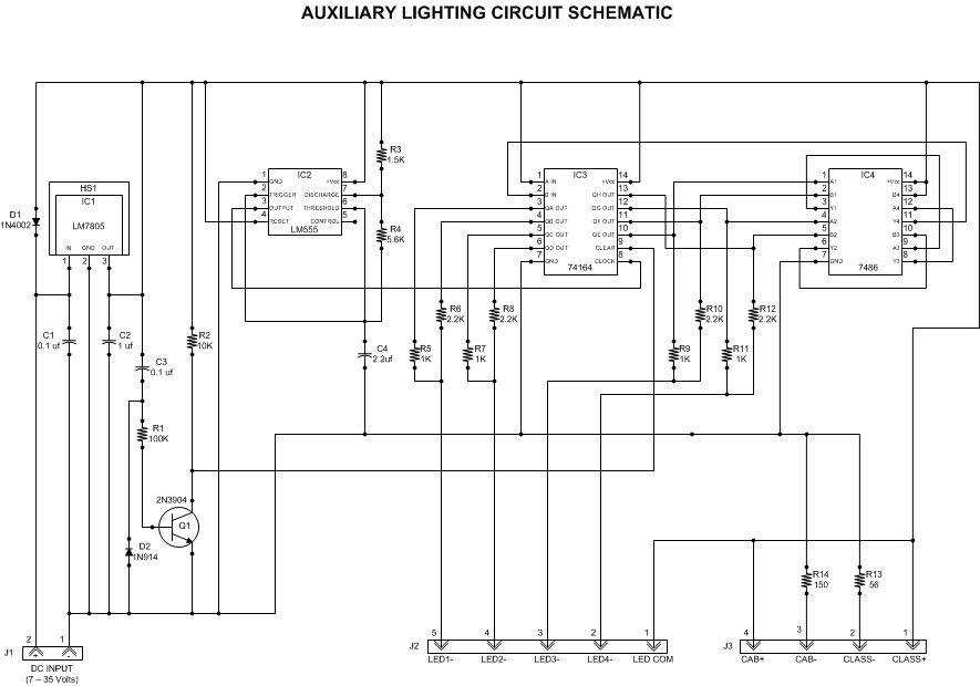
This article outlines a lighting circuit designed to create a glowing firebox effect while providing constant illumination for classification lamps and an interior cab light. It includes comprehensive information necessary for constructing the circuit, such as a detailed schematic,...
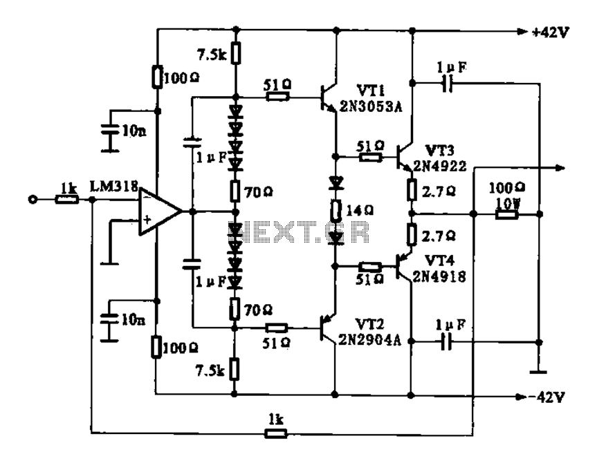
The current amplifier circuit configuration is illustrated in the figure. It consists of a two-stage operational amplifier, the LM318, arranged in a complementary push-pull amplifier configuration, which exhibits low output resistance and possesses load capacity features. The current amplifier circuit...
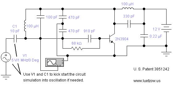
The oscillator circuits presented on this page are derived from expired or non-maintained U.S. Patents. All circuits are formatted for "Electronic Workbench 5.12" or "Multisim 7" circuit simulation software. A note regarding SPICE simulation of electronic oscillator circuits: all...
This circuit illustrates a Lie Detector Circuit Diagram. It is based on the principle that a person's skin resistance varies when they experience emotional stress. The Lie Detector Circuit operates on the principle of galvanic skin response (GSR), which measures...