
preamp HF VHF UHF SHF wideband MAR6
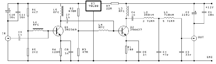
For optimal performance, it is recommended to position the preamplifier as close to the antenna as possible, ideally mounted directly at the feeder (dipole) and utilizing phantom-type powering for the amplifier. The RF/DC splitter should be located inside the shack, just prior to the receiver. It is crucial to maintain short connections at RF IN and RF OUT, ensuring a consistent 50 Ohm impedance starting from the IC leads. The device should be housed in a shielded enclosure.
When used in conjunction with a transceiver, the preamplifier offers a degree of protection against accidental transmission (up to +/- 5 watts) at the output; however, no guarantee is provided that the MAR-6 will withstand such conditions. Precautions should be taken to prevent damage when used in a transmitting scenario (e.g., between the antenna and transceiver). An RF-sensing circuit is recommended for this purpose.
If the antenna already incorporates a static bleeder (or is DC shorted, such as a folded dipole), the inductor L2 can be omitted. To verify this, an ohmmeter can be used to measure the resistance between the center conductor and the braid of the coax, which should read below 1 kΩ. Inverted parallel diodes may also be employed to dissipate static buildup, and testing with a diode tester is advisable. Occasionally, older types of RX verticals may utilize a neon bulb, which cannot be measured; thus, keeping L2 in place is advisable as it poses minimal risk in the aforementioned scenarios.
Connections should be kept as short as possible at RF IN and RF OUT, maintaining a consistent +/- 50 Ohm impedance starting from the leads, and the device should be installed in a shielded casing to minimize interference and enhance performance.The MAR6 (MSA-0686, 0685, 0885) is a high performance silicon bipolar Monolithic Microwave Integrated Circuit (MMIC) housed in a low cost, surface mount plastic package. This MMIC is designed for use as a general purpose 50 W gain block. Applications include narrow and broad band IF and RF amplifiers in commercial and industrial applications.
The MS A-series is fabricated using HP ’s 10 GHz fT, silicon bipolar MMIC process which uses nitride self-alignment, ion implantation, and gold metallization to achieve excellent performance, uniformity and reliability. The use of an external bias resistor for temperature and current stability also allows bias flexibility.
It is a Cascadable Silicon Bipolar The best place to put a pre-amplifier is with out a doubt as closest to the antenna as possible. If possible, directly mounted at the feeder (dipole) and using phantom-type powering of the amplifier.
The RF/DC splitter comes inside the shack just before your receiver. Keep the connections as short as possible @ RF IN and RF OUT and keep them in 50 Ohms impedance starting at the leads from the IC. Mount it in a shielded casing. With use with an transceiver: This preamp is protected to a certain degree for accidental TX (+/- 5watt) at the output, but no guarentee is given that your MAR-6 will survive.
So make the needed precautions to prevent this from occuring when used in a TX type situation (like between your antenna and transceiver). Use a RF-sensing circuit instead. L2 can be left out if your antenna has already some type of static bleeder build in (or DC shortened, like a folded dipole etc.
). If you don`t know for sure, just take your Ohm-meter and measure between the centre and the braid of the coax which should read something like < 1k or so. Inverted parallel diodes are also used to bleed of static build up. Test this with your diode tester. Ever so now and then (mostly with older type of RX verticals) a neon bulb is used hence never can be measured.
Just leave L2 as it is (can`t do much harm in any case stated above anyway). Notes: keep the connections as short as possible @ RF IN and RF OUT and keep them in +/- 50 Ohms impedance starting at the leads. Mount it in a shielded casing. 🔗 External reference
Related Circuits
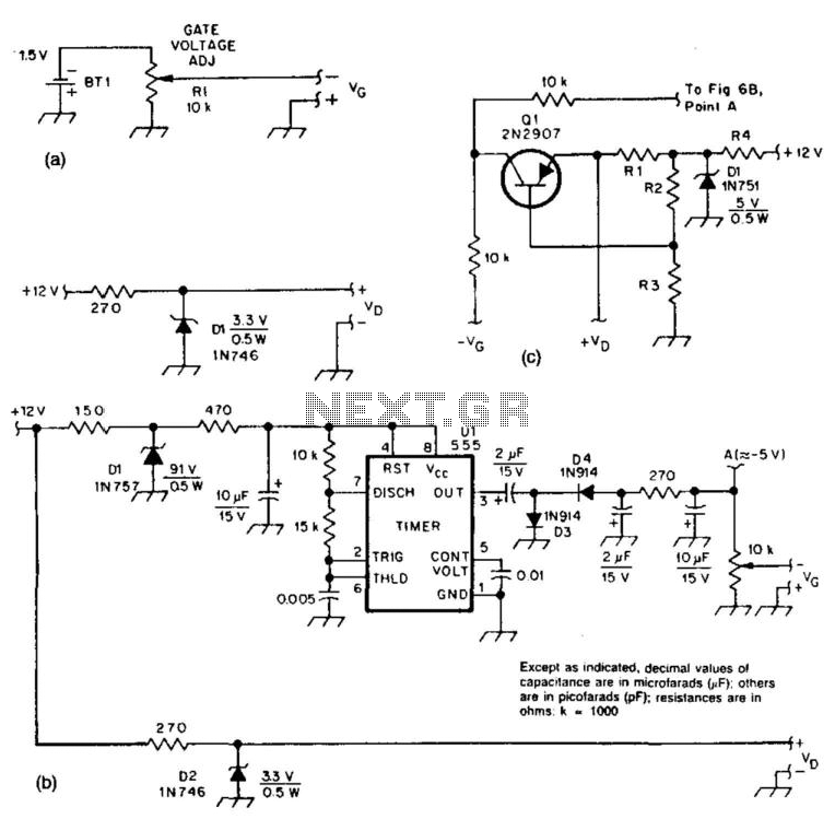
These two circuits provide bias for the microwave preamplifiers discussed in this text. The circuit in Figure 51-5(a) is a simple passive power supply. Figures 51-5(b) and 51-5(c) represent active power supplies, with Ul generating a negative supply and...
The diameter of the antenna elements can range from 5.8 mm, while the dipole diameter can vary from 8 mm to 12 mm, with 12 mm being the recommended size. This adjustment can be made without altering the length...
A high-efficiency, simple two-transistor VHF amplifier electronic circuit project can be developed using the provided circuit diagram. This VHF amplifier circuit achieves a significant efficiency with a gain of approximately 16 dB and does not require any tuning or...
This UHF wideband amplifier (Ultra High Frequency amplifier) provides a total gain of 10 to 15 dB in the frequency range of 400 to 850 MHz, making it suitable for areas with weak TV signals. For optimal performance, the...
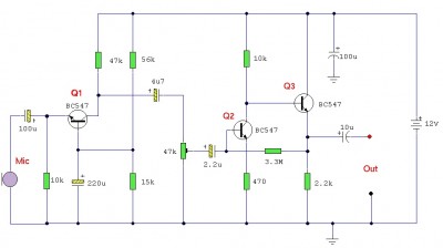
This is an audio preamplifier for dynamic microphones with an output impedance of 200-600 ohms and a low-noise pre-amplifier ideal for signal strengthening. It features a three-stage discrete amplifier with gain control. Transistor alternatives such as BC109C, BC548, BC549,...

These circuits are useful for video applications up to 10 MHz. The 3.3-pF capacitors serve as compensation capacitors. The capacitors connected to pins 7 and 4 act as bypass capacitors to prevent self-oscillations. Figure 76-18(a) illustrates a non-inverting configuration,...
Warning: include(partials/cookie-banner.php): Failed to open stream: Permission denied in /var/www/html/nextgr/view-circuit.php on line 713
Warning: include(): Failed opening 'partials/cookie-banner.php' for inclusion (include_path='.:/usr/share/php') in /var/www/html/nextgr/view-circuit.php on line 713