
Dual edge triggered circuit diagram

The 9602 multivibrator is a versatile component commonly used in timing applications and signal generation. It is capable of functioning as a monostable or astable multivibrator, depending on the configuration of external components. In a typical setup, the circuit can be designed to respond to changes in the input signal, specifically the rising and falling edges of a square wave.
To achieve double-edge triggering, the circuit requires the addition of two resistors (R1 and R2) and a capacitor (C1). The configuration allows the multivibrator to respond to both edges of the input signal. When the input signal transitions from low to high (rising edge), the circuit produces a corresponding output pulse. Conversely, when the input signal transitions from high to low (falling edge), the capacitor C1 discharges, creating a negative pulse that triggers the 9602, resulting in another output pulse.
The values of the resistors and capacitor must be selected carefully to ensure the desired timing characteristics and pulse width of the output signal. The timing period can be calculated using the formula: T = 0.7 * (R1 + R2) * C1, where T is the output pulse width. This flexibility allows the 9602 multivibrator to be integrated into various applications, such as waveform shaping, frequency division, and pulse generation in digital circuits.
In conclusion, the 9602 multivibrator circuit is a robust solution for generating precise timing signals and can be adapted for double-edge triggering through the addition of external components. Proper component selection and configuration are essential for achieving the desired functionality in electronic designs.Typically, 9602 multivibrator circuit can trigger the rising edge or falling edge of the square wave, but not both at the same time can trigger the use of two additional resistor and a capacitor can trigger a double edge. When the input decreases, C1 through negative pulse trigger to 9602, to produce the output pulse.
Related Circuits
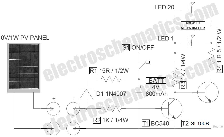
The circuit for the LED solar lantern lights is designed using a 6V/1W solar panel (photovoltaic panel) and a 4V/800mAh lead-acid battery. The schematic for the LED solar lantern circuit incorporates a solar panel that converts sunlight into electrical energy....
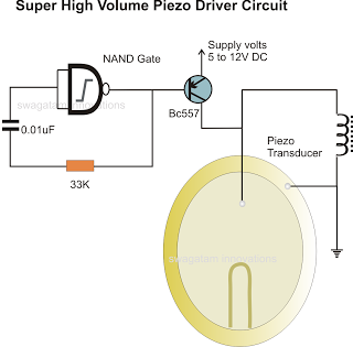
In the previous post, a piezo transducer element was discussed, along with its application in electronic circuits. This article will explore how a piezo transducer can be driven or operated using a simple circuit. The amplification method differs from...
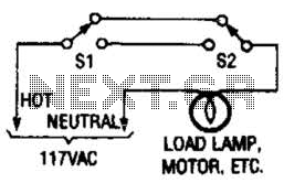
This switching arrangement is utilized in both domestic and industrial environments to enable control of a light or other AC-operated device from multiple locations. This switching arrangement, commonly referred to as a multi-way switching system, is designed to facilitate the...
If time was spent experimenting with the ALF type SE circuit, some shortcomings related to a Power Smart Head adaptation may have been discovered. The issue arises because HCMOS gates consume significant power when utilized as SE voltage comparators,...

Bicycle tire leak detector circuit schematic. The circuit detects air leaks in car tires caused by sharp objects. It uses a microphone (BM) to capture the sound of escaping air, which is then converted into an electrical signal. This...
The circuits examined thus far rely on linear feedback for their operation. The magnitude of the signal returned to the negative input is always strictly proportional to the output voltage. Consequently, within the limits defined by the operational amplifier...