
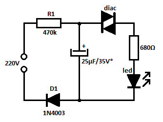
220 V LED Night light
It is highly recommended to use the original capacitor rated for DC-200 or 250 V, with an AC peak value of about 230 V and 320 V. When using a capacitor with a DC voltage indication, it should be rated for 400 V or more. A capacitor rated for 250 V or even 200 V may be overloaded and could eventually fail. The current through the LEDs when the switch is closed is about 18 mA, allowing the LEDs to emit sufficient light for reading. When the switch is open, the current decreases to only a few hundred microamperes, resulting in a light intensity that corresponds to the brightness of a few tubes.
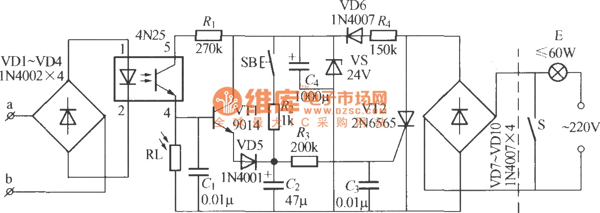
The circuit design incorporates a capacitor (C1) for energy storage, which is essential for smoothing out voltage fluctuations. The Zener diode serves a dual purpose: it protects the LEDs from high voltage spikes and regulates the voltage to a safe level. The resistors (R2 and R3) are critical for current limiting, ensuring that the LEDs operate within their safe current ratings. Overall, this capacitor power supply circuit is designed for efficiency and reliability, with careful consideration of component ratings and operational limits to prevent damage to sensitive components like LEDs.This Is a capacitor power supply. This is a very small currents of energy-effective, because it has very little loss, much smaller than the miniature transformer. Capacitor impedance is inversely proportional to frequency. This is a great disadvantage when the grid appear in the short interference pulses caused by switching on large appliances with inductive load character.
For such a limiting pulse capacitor (C1 here) is practically a short circuit and load through a short period of much higher current. LEDs are the glitches very sensitive and easily damaged or destroyed directly. Current pulses damaged LED is rated at significantly less power and small streams are starting to shine from a stream. Oshin especially white LEDs will be damaged very easily. Therefore, the circuit is completed by the Zener diode and resistors R2 and R3. Resistor R2 limited to a maximum pulse current of 300 mA. Zener diode for reducing interference pulse voltage of 12 V and resistor R3 ensures that the LED current will not flow more than 40 mA, LED after a short period of time without lasting damage.
When connected correctly, the circuit components should work on first connection. If you're not sure you're getting involved in correctly, try the following parts of the circuit at low voltage. First connect the regulated power to the Zener diode in accordance with the polarity of the electrolytic capacitor.
Slowly zoom voltage. When voltage is about 6 V would be to light up the LEDs. When voltage is about 11 V should be a current consumption of about 30mA. When voltage is about 12 to 13 in the current consumption should increase sharply, because the current will pass through the zener diode. Tension just zoom into the current 100-200 mA. Do not worry about big long zener diode current, could be destroyed. Then connect the source to the rectifier to the terminals marked with a tilde. The device should behave the same, only all voltages will be about 1 V greater. Connect the power rectifier with the opposite polarity. The circuit should work as well as in the previous case. Finally, still make sure that no shunt capacitor C1. At the outlets you have just measured the resistance parallel connected resistor R1. If everything is right, fitting casing cover, turn the switch so as to open and plug the device into an AC outlet.
LED should light up with little brightness. When the switch is closed should be lit to the fullest. The facility is in operation electrically connected to the network, keep working so caution should be exercised. Author not responsible for any shock. Highly recommend using the original capacitor, which is DC-200 or 250 V AC peak value is about 230 V and 320 V when using a capacitor with an indication of DC voltage should be 400 or more voltage 630 V Capacitor 250 V or even 200 V voltage is overloaded and can eventually break through.
The switch is current through the LEDs is about 18 mA LED light issue so that it can be close to lights and read. By opening the switch is procházající current only a few hundred microamperes and light intensity corresponds to shine more tubes.
🔗 External reference
Related Circuits
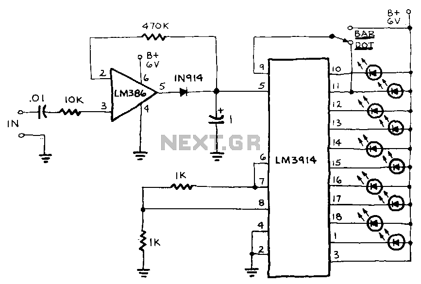
The circuit includes a peak detector that immediately drives the readout to any new higher signal level and slowly lowers it after the signal drops to zero. The readout is a moving dot or expanding bar display. The circuit...
Christmas is approaching, and it is the time of year when electronics students and hobbyists consider creating a Christmas circuit for their homes, particularly one that features flashing lights. Numerous circuits and kits are available that can flash various...
The diagram illustrates an automatic lighting control circuit activated by a telephone. At night, when the telephone rings or the user picks up the receiver, the light turns on. If the telephone stops ringing (when no one is listening)...
The 555 circuit below is a flashing bicycle light powered with three C or D cells (4.5 volts). The two flashlight lamps will alternately flash at an approximate 1.5 second cycle rate. Using a 4.7K resistor for R1 and...
The turn signals, hazard lights, stop lights, and headlights are functioning properly. However, the tail lights do not operate when the headlights are on. The bulbs appear to be in good condition, as they were tested by switching the...
This is likely the simplest concept for generating a flashing light from an LED using alternating current (AC). The circuit provides a straightforward method for flashing one or more LEDs using high-voltage direct current (DC) sourced from mains electricity....