
220v ac operated christmas light star

The circuit design employs a combination of discrete components to achieve a reliable 5V DC supply, which is crucial for the operation of the multivibrator and the triggering of the triac. The inclusion of diodes D1 and D2 ensures proper rectification and protection against reverse polarity, while the zener diode ZD1 stabilizes the voltage to maintain a consistent output under varying load conditions.
The multivibrator configuration, consisting of two BC548 transistors, operates in an astable mode. The resistors R3 through R7 and capacitors C4 and C5 dictate the timing characteristics, allowing for precise control over the output frequency. This frequency modulation is essential for the desired operation of the connected load, in this case, a lamp.
Transistor T3 serves as a switch that amplifies the output signal from the multivibrator to drive the triac BT136. The LED1 acts as an indicator, providing visual feedback when the triac is activated. The triac, once triggered, allows current to flow through the connected lamp, thus illuminating it during the positive half cycles of the output signal.
The overall design is cost-effective, with an estimated total expense of Rs 75, making it an economical solution for applications requiring a controlled lighting mechanism. The schematic effectively integrates the components to ensure reliable performance and operational efficiency.Components like resistors R1 and R2, capacitors C1, C2, and C3, diodes D1 and D2, and zener ZD1 are used to develop a fairly steady 5V DC supply voltage that provides the required current to operate the multivibrator circuit and trigger triac BT136 via LED1. The multivibrator circuit is constructed using two BC548 transistors (T1 and T2) and some passive components. The frequency of the multivibrator circuit is controlled by capacitors C4 and C5 and resistors R3 through R7. The output of the multivibrator circuit is connected to transistor T3, which, in turn, drives the triac via LED1.
During positive half cycles of the multivibrator`s output, transistor T3 energises triac BT136 and the lamp glows. This circuit is estimated to cost Rs 75. 🔗 External reference
Related Circuits
The schematic of the SAVER V3.2 is depicted in Figure 1. A transformerless power supply uses Xc of a 0.22uF capacitor to limit current, providing about 10mA current source. The diodes rectify AC current to DC current, which in...
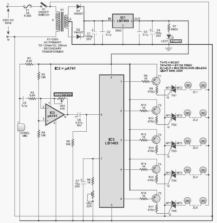
This light chaser circuit, which functions as a music-operated lighting effect generator, consists of five sets of 60W bulbs arranged in a zig-zag configuration. The light chaser circuit is designed to create dynamic lighting effects that synchronize with music, enhancing...
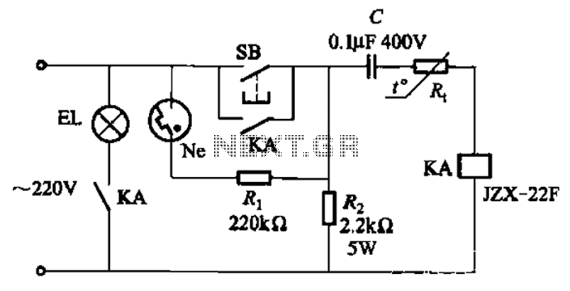
The circuit illustrated in Figure 2-49 is straightforward, featuring a cold Positive Temperature Coefficient (PTC) thermistor element. It utilizes the thermal resistance characteristics of the lamp to manage the delay time, which typically ranges from 10 to 30 seconds....

The circuit is depicted in Figure 1, while the electrical schematic diagram is presented in Figure 2. The AC voltage of 220V is reduced by components C3 and R3. The diodes VD1 and VD2 rectify the voltage, and capacitors...
When the circuit is connected to hi-fi equipment or at both ends of the electronic instrument's speaker, the audio level can be modulated to a 500W lamp proportionally. This is achieved using three appropriate sets of audio filters and...

The circuit is designed to ensure that the headlights or side lights are automatically switched off after the ignition contact is turned off. This prevents the occurrence of a dead battery due to headlights being inadvertently left on. The circuit...