
LED
The described circuit employs a TRIAC for controlling AC loads, making it suitable for applications where dimming or light sensitivity is desired. The TRIAC allows for the control of the power delivered to the load by varying the phase angle of the AC signal. This method of control is efficient for light dimming applications, as it reduces power consumption while providing a smooth transition in brightness levels.
The LDR serves as a light sensor that adjusts the output based on ambient light conditions. In low-light conditions, the resistance of the LDR decreases, allowing more current to flow through the TRIAC, thereby increasing the brightness of the connected lamp. Conversely, in bright conditions, the resistance of the LDR increases, which reduces the current flowing through the TRIAC, dimming the light.
To enhance the sensitivity of the circuit, the fixed resistor can be substituted with a variable resistor (potentiometer), allowing for manual adjustment of the light sensitivity threshold. This feature enables users to customize the operation of the light switch according to their specific lighting environment.
Installation considerations are critical for optimal performance. The placement of the LDR should be strategic, ensuring that it is shielded from direct light emitted by the lamp to avoid erroneous readings and unintended dimming behavior. Proper housing or shielding can be employed to maintain the integrity of the sensor's readings.
Overall, this circuit represents a practical solution for automatic light control, combining simplicity in design with effective functionality, making it a valuable addition to home automation systems.The series of light switches this time slightly different from the voltage of work. The series of light switches can work directly on the AC power network. Light switches are using the main component of TRIAC and LDR. The circuit is very simple and the components were sold in the market. If you want a light reception sensitivity of this circuit ca n be arranged then the 3. 3 MOhm resistor can be replaced with a variable resistor. For more details can be seen from the following series of images. With Triac Light switch series is as dimers, but dimers control performed by the reception of light around the LDR. The lower the intensity cayaha received LDR then bright lights. For installation LDR need to be considered so as not exposed to light from the lamp directly. 🔗 External reference
Related Circuits
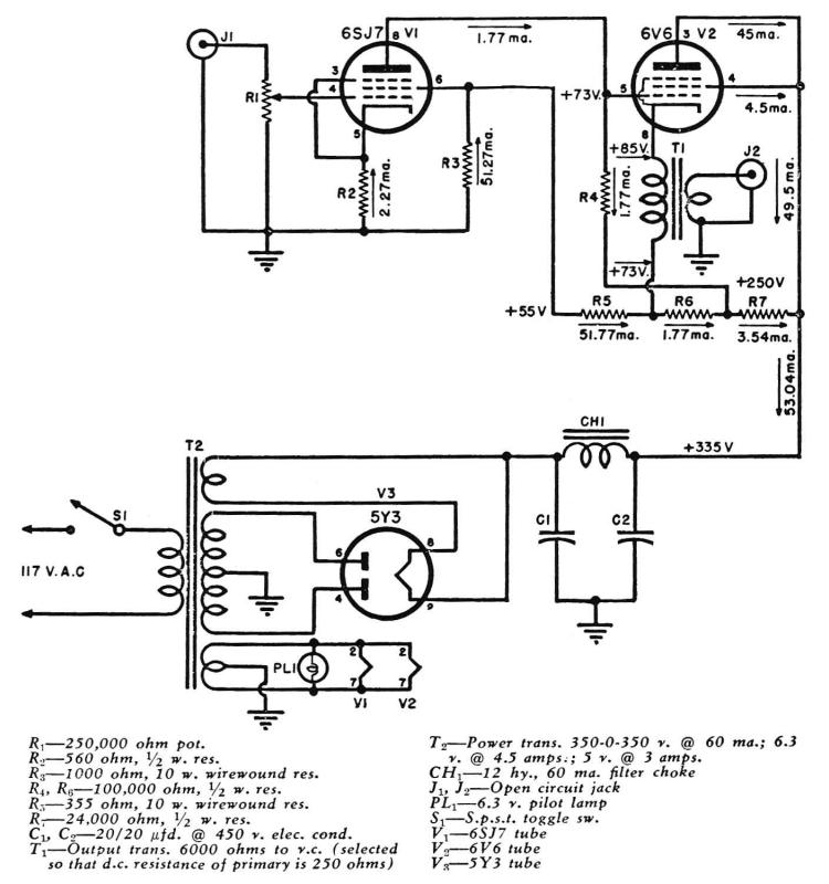
A Direct-Coupled 6V6 Tube Amplifier with Cathode Follower by Raymond H. Bates from Radio & Television News magazine, November 1949. The Direct-Coupled 6V6 Tube Amplifier is designed to utilize a 6V6 vacuum tube, which is known for its warm sound...
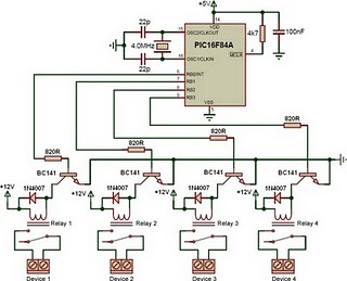
This is a relay driver based on a PIC16F84A microcontroller. The board includes four relays, allowing control of four distinct outputs. The relay driver circuit utilizing the PIC16F84A microcontroller is designed for controlling multiple devices or systems through relay activation....
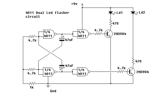
This simple circuit utilizes NAND gates to alternately flash two LEDs. The two 47µF capacitors set the flashing frequency. It is advisable to include a decoupling capacitor across the power supply. The circuit was constructed using the specified components...
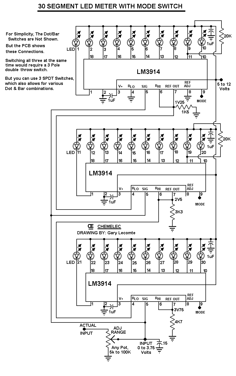
The circuit can be easily configured for full-scale voltages of either 20 or 200 volts by utilizing a suitable potentiometer on the input. It is critical not to exceed 30 volts at pin 5 of the LM3914. A 20...
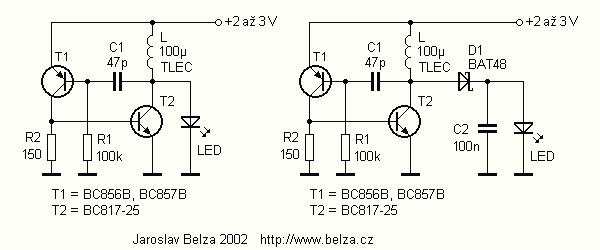
The article describes a simple and very cheap to drive white, blue or UV LEDs, used for example in small lamps and testers. The cost of components shall not exceed CZK 10. Converters for white LED has been on...
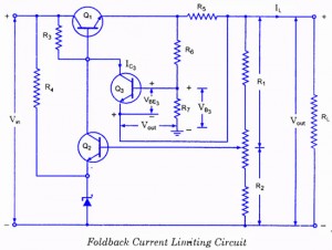
If the load resistance (RL) is reduced or the load terminals are accidentally shorted, a very large load current will flow, potentially damaging the pass transistor (Q1), diode, or other components. Fuse protection may not be sufficient, as the...