
Ultra low noise preamplifier

The SL561 preamplifier is engineered to amplify weak audio or video signals with minimal added noise, making it suitable for high-fidelity applications. Its design features a high input impedance, allowing it to interface effectively with various signal sources without loading them down. The preamplifier's gain can be adjusted by varying the capacitance (C1) and resistance (RSET) components in the circuit, which are critical for optimizing performance across the specified frequency range.
In practical applications, the circuit may include additional components such as bypass capacitors to filter out power supply noise, and feedback networks to stabilize gain and improve bandwidth. The output stage of the SL561 typically drives subsequent stages in the signal chain, such as filters or analog-to-digital converters, ensuring that the amplified signal maintains integrity and fidelity.
Figures referenced in the description provide essential visual data for understanding the performance characteristics of the SL561. The gain versus frequency plot (Figure 2-6B) is crucial for determining the operational bandwidth of the preamplifier, while the gain versus RSET (Figure 2-6C) assists in selecting appropriate resistor values for desired gain settings. The electrical characteristics (Figure 2-6D) offer insights into parameters such as supply voltage, input/output impedance, and power consumption, which are vital for system integration. Finally, the harmonic distortion graph (Figure 2-6E) is important for assessing the linearity of the amplifier and its suitability for high-quality audio or video applications.
This circuit exemplifies the essential role of preamplifiers in signal processing, particularly in scenarios where signal integrity and low noise are paramount. Proper selection and configuration of the SL561 and its associated components can significantly enhance system performance, making it a valuable asset in audio/video electronics design.The SL561 used in this circuit is a high-gain low-noise preamplifier designed for audio/video applications at frequencies up to 6 MHz. Figure 2-6B shows gain versus frequency for various values of C1, and Fig. 2-6C shows gain versus various values of RSET. Figure 2-6D shows the electrical characteristics. Figure 2-6E shows harmonic distortion. 🔗 External reference
Related Circuits
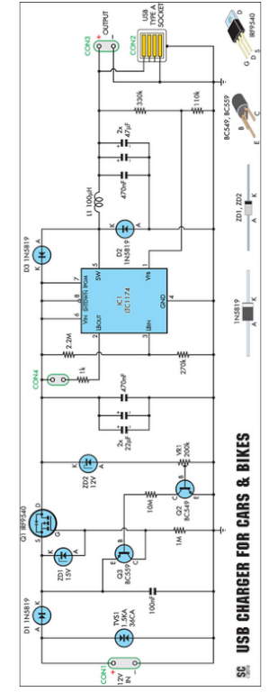
Seeking an efficient USB charger capable of operating from a 12V car battery? This unit operates at up to 89% efficiency and can charge USB devices effectively. This USB charger circuit is designed to convert a 12V car battery supply...
Interest in creating an antenna rig suitable for use with a handheld transceiver for fox hunting. Suggestions are sought for a cost-effective yet efficient solution. To create an effective antenna rig for fox hunting using a handheld transceiver (HT), several...
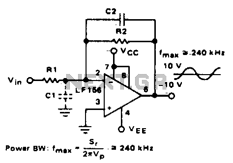
Parasitic input capacitance (ICi) is 3pF for LM5S, LF156, and LF157, along with any additional layout capacitance. This interacts with the feedback element and creates undesirable high-frequency effects. To mitigate this, a capacitor (C2) should be added in conjunction...
Ultrasonic Switch. A circuit of a new type of remote control switch is described here. This circuit operates with inaudible sound waves. The ultrasonic switch operates by utilizing ultrasonic frequencies, which are sound waves above the range of human hearing...
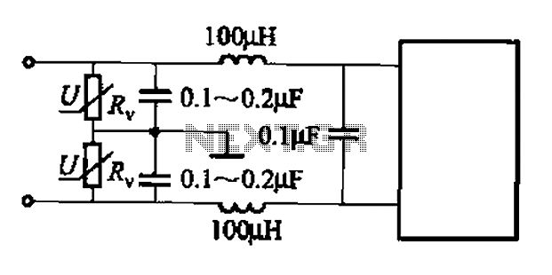
A common low-pass filter circuit is illustrated. Figures (a) to (c) demonstrate its ability to suppress high-frequency interference, while Figure (b) shows a varistor that can absorb lightning surge voltage. Figure (d) indicates the circuit's capability to suppress low...
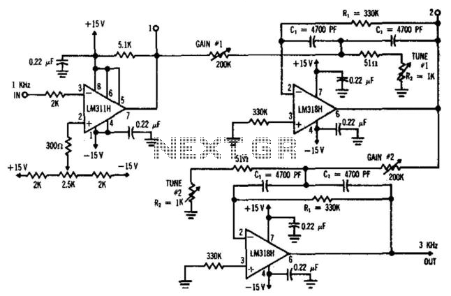
This circuit utilizes a comparator configured as a Schmitt trigger (311H) along with two active bandpass filters (LM318H) to achieve a 3-kHz output. Higher odd harmonics can be generated by adjusting the active filters to the desired frequency, such...