
Automatic Car/Vehicle Head Lights Turn Off Circuit
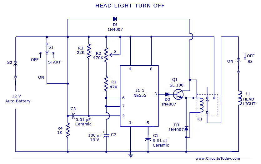
The described circuit utilizes the 555 timer IC in a monostable configuration to achieve the automatic switching function. In this setup, the 555 timer is triggered by a momentary switch, which can be connected to the vehicle's ignition system or a dedicated switch on the dashboard. Upon activation, the timer begins its timing cycle, which is determined by an external resistor-capacitor (RC) network connected to the timing pins of the IC.
The timing period can be adjusted by selecting appropriate resistor and capacitor values. For instance, the time delay (T) can be calculated using the formula T = 1.1 × R × C, where R is the resistance in ohms and C is the capacitance in farads. This flexibility allows the user to set a delay period ranging from a few seconds to several minutes, depending on the application requirements.
Once the preset time elapses, the output pin of the 555 timer transitions from a high state to a low state. This output can be used to control a relay or a transistor, which in turn disconnects the power supply to the vehicle's headlights or lamps. The relay or transistor must be rated appropriately to handle the current required by the vehicle's lighting system.
Additional components may include a diode across the relay coil to prevent back EMF from damaging the 555 timer when the relay is deactivated, as well as capacitors for power supply decoupling to ensure stable operation of the timer. The circuit can be powered from the vehicle's battery, with considerations for voltage levels and current ratings to ensure reliability and safety.
This automatic headlight switch-off circuit enhances vehicle safety by preventing battery drain and ensuring that lights are not left on inadvertently when the vehicle is parked.A circuit that can turn off head lights/lamps of a car/vehicle automatically after a preset time.This light switching circuit is built using 555 timer IC.. 🔗 External reference
Related Circuits

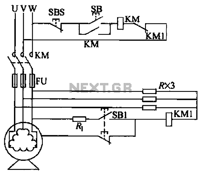
The utility vehicle anti-theft alarm circuit consists primarily of two main components essential for its operation. The security circuit is activated when the vehicle owner departs from the vehicle, utilizing an anti-theft switch (S B) to engage the alarm...
A voltage leakage protection circuit utilizing a resistive element as an auxiliary neutral point is illustrated in the accompanying figure. When selecting the resistance, it is essential to consider both the resistance value and power consistency. The described voltage leakage...
The design objective was to produce an hFE tester with switched collector currents for the DUT (Device Under Test) covering a range suitable for the selection and matching of output transistors for amplifiers such as the JLH Class-A, ESP...
The LM2002 / 2002A is an audio power amplifier integrated circuit. The LM2002A features high voltage protection, with a maximum instantaneous power supply voltage of up to 40V, and comes in a 5-pin single in-line plastic package. This integrated...
Solar battery charger schematic and description. This solar battery charger circuit is capable of charging a 12V lead-acid battery or sealed lead-acid (SLA) battery. The solar battery charger circuit is designed to convert solar energy into electrical energy for charging...
This complete high quality, low noise 5-BAND GRAPHIC EQUALIZER circuit is based around Monolithic Linear integrated circuit LA3600 manufactured by SANYO. This circuit is very easy to build and has good Quality. You can use it with Portable component...