
LCD series microprocessor circuit diagram of speech synthesis
The speech synthesis circuit is designed to generate human-like voices from textual input, making it suitable for various applications that require vocal output. The core component, a microprocessor, handles the processing of speech data and controls the overall functionality of the circuit. The integration of LCD drivers allows for visual output, displaying relevant information or messages alongside the audio output.
The clock oscillator is crucial for timing operations within the circuit, ensuring that audio playback is synchronized accurately with other functions. Input and output ports facilitate user interaction and connection to other devices, enabling features such as voice recording and playback, as well as control over volume and other audio parameters.
Memory components are essential for storing speech data, allowing the circuit to reproduce a range of voices and phrases. The multi-voice audio signal amplifier enhances the audio output, ensuring that the synthesized speech is clear and audible.
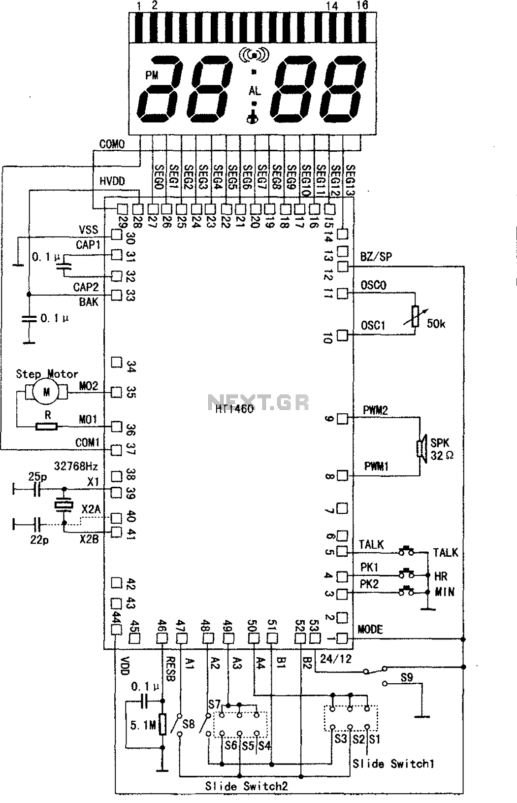
This circuit is particularly effective in applications such as voice clocks, where it announces the time audibly, and in electronic thermometers that provide verbal temperature readings. Additionally, it can be used in electronic calendars that vocalize events and reminders, as well as in intelligent voice toys that interact with users through speech. The HT1460 serves as a reference design, showcasing the typical configuration and connections required for implementing this speech synthesis functionality in various electronic devices.The speech synthesis circuit embedded microprocessor series, LCD drivers, clock oscillator, input and output ports, memory and multi-voice audio signal amplifier circuit unit. This series circuit is mainly used for voice clocks, thermometers, electronic calendar, intelligent voice toys. As shown in the typical application circuit HT1460.
Related Circuits
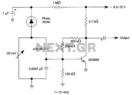
The circuit utilizes a tuned circuit for frequency selection, designed to operate at approximately 51 kHz. The 2N3565 transistor amplifies the output generated by the tuned circuit. The described circuit operates on the principle of resonance, where the tuned circuit...
This circuit gradually illuminates a 120VAC lamp over an approximate 20-minute period. A bridge rectifier converts the AC voltage to 120V DC, supplying power to the MOSFET and the 60-watt lamp. A 6.2K, 5-watt resistor along with a Zener...
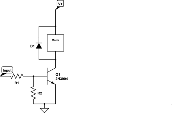
Control a small 5V motor using an external power supply by triggering a transistor with an Arduino. The transistor in use is an NPN type, specifically the 2N3904. To control a small 5V motor using an Arduino and an NPN...
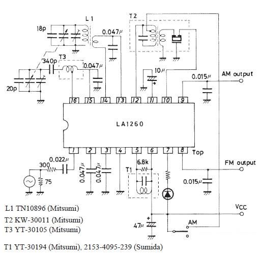
A very simple FM IF MW radio receiver circuit can be designed using the LA1260 IC manufactured by Sanyo Semiconductor. This FM IF MW radio receiver circuit schematic shows that the LA1260 IC can be utilized in AM and...
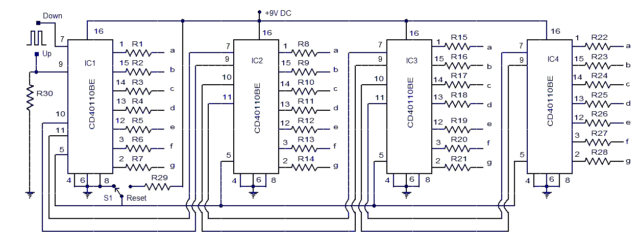
This circuit diagram illustrates a simple up/down counter suitable for various applications. It utilizes the CD40110BE IC, a CMOS decade up/down counter. Common cathode seven-segment displays are connected to the outputs of each IC. The display connected to IC1...
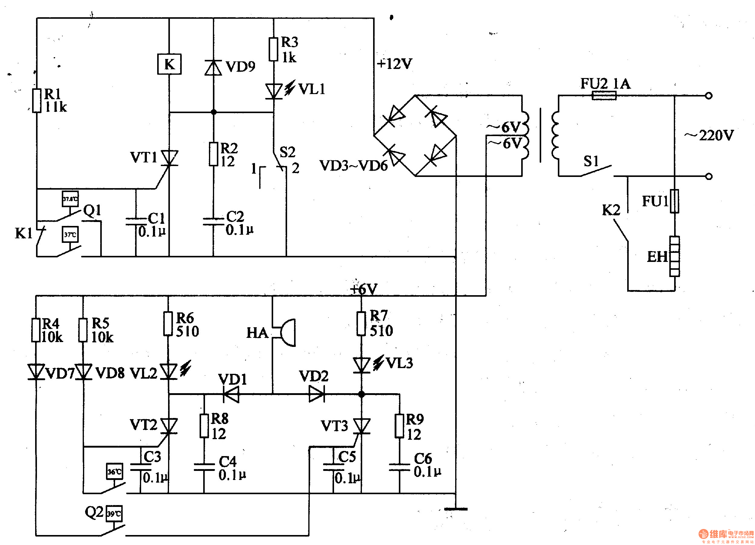
The egg hatching incubator circuit comprises a power supply circuit, a constant temperature control circuit, and a sound and light alarm circuit, as illustrated in Figure 4-7. The power supply circuit includes a power switch (S1), a fuse (FU2),...