
25 LED Sequencer schematic

This circuit is designed to drive a series of 25 small Christmas lights, each operating at approximately 200mA and 3 volts. The circuit utilizes a 5-volt supply, which is essential for proper operation. The 4017 decade counter is employed to sequentially activate the lights, but it experiences a voltage drop of about 1 volt at its output when driving the 2N3053 NPN transistors.
The configuration of the transistors is such that the emitters will have a voltage approximately 0.7 volts lower than the base voltage. This drop is typical for bipolar junction transistors (BJTs), resulting in a final voltage of about 3 volts across each lamp, which is necessary for optimal brightness. The circuit allows for the adjustment of the supply voltage to achieve the desired current through the lights, providing flexibility in operation.
In terms of components, small diodes rated for at least 500mA are required to be placed in series with each light to protect against reverse polarity and ensure proper current flow. The 1N4001 diode is a suitable choice for this application due to its reliability and capacity to handle the required current.
For the transistor selection, while various NPN transistors can be employed, the 2N3053 has been found to perform better due to its higher gain characteristics compared to the 2N2219A. However, both transistors are viable options for this circuit, allowing for some degree of interchangeability based on availability and specific design requirements.
Overall, this circuit effectively demonstrates the principles of driving a load with a microcontroller or counter while incorporating necessary protective components to ensure longevity and reliability of the light display.This circuit is same as the above setup to drive 25 small Xmas lights. The lights operate at about 200mA and 3 volts. The supply voltage is set to 5 volts and the 4017 counter output will drop about a volt using the 2N3053 transistors. The voltage on the emitters of the rows transistors will be about 0.7 volts less than the base so the lamp voltage will be about 3 volts.
You can adjust the supply voltage for the desired current if necessary. It works the same way as the LED version but you need diodes in series with each light. Most any small diode rated at 500mA or more should work. I used 1N4001 diodes. Various NPN transistors can be used, I tried 2N2219A and 2N3053. The 2N3053 worked out better with a higher gain than the 2N2219A, but either one should work. 🔗 External reference
Related Circuits
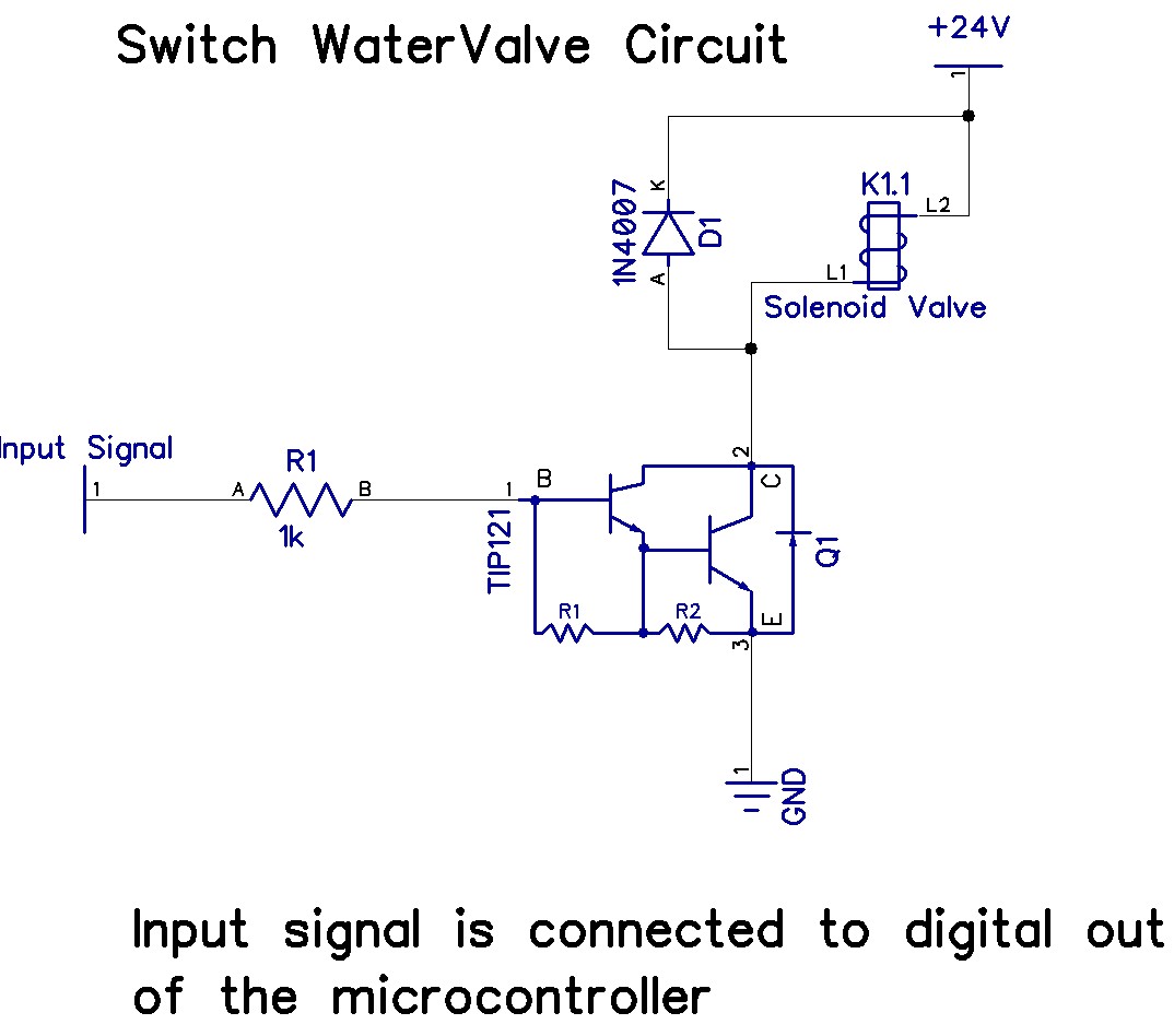
The Arduino Uno has adequate memory and ports, but efficient programming is necessary to store settings in memory. The Mega version offers increased memory and ports. The Shako valve operates on 24 volts DC; however, 12 volts is preferred...
A common issue encountered is that individuals possess a schematic, also known as a circuit diagram, that they wish to construct. However, they discover that there are... Building a circuit from a schematic requires a clear understanding of the components...
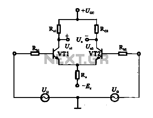
An emitter-coupled differential amplifier circuit is designed to suppress zero drift through circuit symmetry. The effectiveness of zero drift suppression improves with better symmetry; however, in practice, achieving complete symmetry is not feasible. Consequently, the basic differential amplifier circuit...
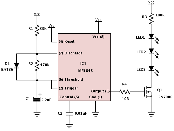
A basic circuit of the 89C2051 can be constructed using point-to-point soldering on a universal printed circuit board (PCB). An ordinary 20-pin socket should be utilized, avoiding the use of a circular-pin socket. D1 represents a small dot LED....
The two unspecified polarized capacitors (one directly above the transformer and one directly to the right of the transformer) are actually each a pair of 470 µF capacitors in parallel (for a total of four 470 µF capacitors). These...
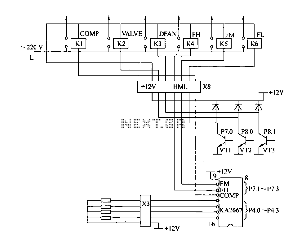
The driving circuit depicted in Figure 18-12 consists of a connection between the driving portion, the microcontroller, and the air conditioning operation components of the bridge. The microcontroller's digital signal levels from ports P4.0 to P4.3 (approximately 12 feet)...