
AT89C2051/4051 Driving Dot LED
The circuit design for the 89C2051 microcontroller is straightforward and suitable for prototyping and educational purposes. The 89C2051 is an 8-bit microcontroller from the 8051 family, which provides a robust platform for various applications. The use of point-to-point soldering on a universal PCB allows for flexibility in layout and design adjustments.
The 20-pin socket serves as the interface for the microcontroller, ensuring a secure connection while allowing for easy replacement or removal of the chip. The choice of a 7805 or 78L05 voltage regulator (U2) is critical for providing a stable +5V supply, which is necessary for the proper operation of the microcontroller and connected components. The 7805 is a standard linear voltage regulator, while the 78L05 is a low-dropout version, suitable for applications where space and thermal management are considerations.
Incorporating U3 as an optional component for polarity correction can enhance circuit reliability, especially when using a DC adapter. This component can prevent damage to the microcontroller and other sensitive components in the event of incorrect power supply connections.
To ensure the integrity of the circuit before powering it up, it is advisable to check all connections meticulously. Measuring +5V between pin 20 (Vcc) and pin 10 (GND) confirms that the power supply is functioning correctly. Testing the LED (D1) provides a visual indication of the circuit's operational status. By shorting P1.7 to GND, the LED should illuminate, confirming that the microcontroller is executing code and that the output pin is functioning as intended. This simple yet effective test is a practical approach to validating the circuit's performance prior to deploying more complex functionalities.A basic circuit of the 89C2051 shown here can be made easily using point-to-point soldering with a universal PCB. Use an ordinary 20-pin socket, do not use a circle-pin socket. D1 is a small dot LED. U2 can be either 7805 or 78L05. U3 is optional for correcting any polarity DC adapter. Without the 2051 chip in the socket, checks the connection, th en measures +5V between pin 20 and pin 10. Test the LED by shorting P1. 7 pin to GND. 🔗 External reference
Related Circuits
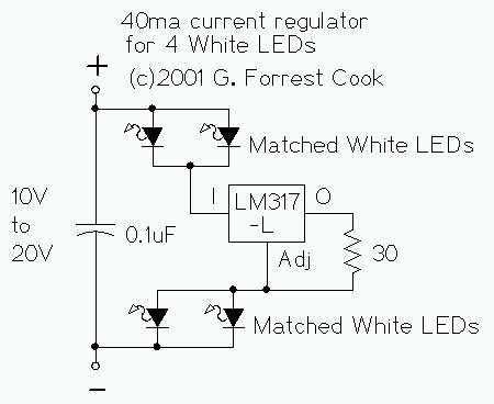
The LM317L and resistor act as a current regulator set to 40ma. Current flows from the battery through one pair of LEDs, through the regulator, through the other pair of LEDs, and back to the battery. The capacitor filters...
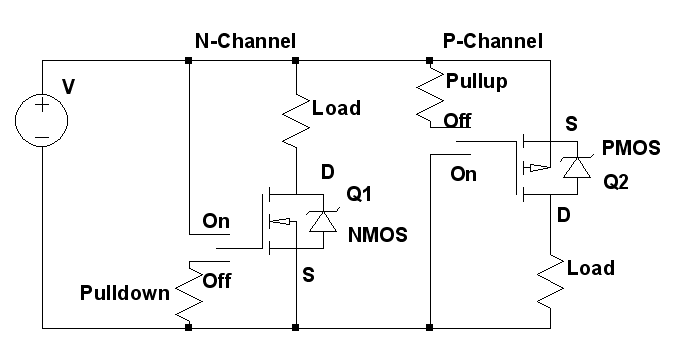
Construct a compact battery-powered device that incorporates a servo motor. The design should include a mechanism to turn off the servo to conserve battery life. It has been noted that MOSFETs can be utilized for this purpose; however, there...
The 555 circuit below is a flashing bicycle light powered with three C or D cells (4.5 volts). The two flashlight lamps will alternately flash at an approximate 1.5 second cycle rate. Using a 4.7K resistor for R1 and...
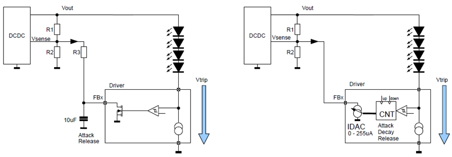
New design techniques in LED driver circuits promise to deliver significant energy savings that will help TV manufacturers meet stringent power consumption requirements. The advancement of LED driver circuits through innovative design techniques has the potential to yield substantial energy...
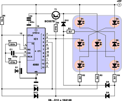
Every DIY enthusiast creates their own electronic dice using LEDs as indicators. This eliminates the need to physically roll dice; instead, a button is pressed. The circuit is designed to prevent any manipulation of the outcome, ensuring fairness. This...
The TL082 (Or a TL072 also is OK) Creates an Adjustable Sawtooth Generator. (It also has a Square wave Output, but it isn`t used here.) The Left and Right LEDs are connected in series, and if this circuit is used...