
Audio Tone Control
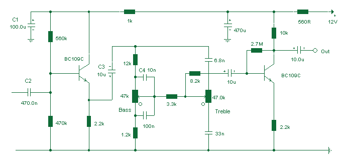
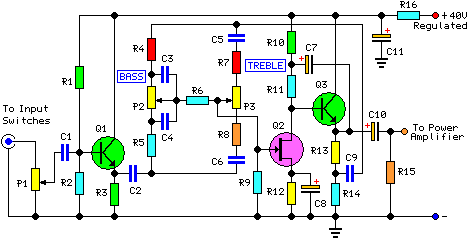
The described circuit is a Baxendall tone control circuit, which is renowned for its ability to adjust audio frequencies with precision while maintaining a flat response at the center frequency. This circuit employs a BC109C transistor as an input buffer, which is critical for maintaining high input impedance and ensuring that the signal is not significantly loaded by the subsequent stages. The input impedance of approximately 250kΩ allows for compatibility with various audio sources without degrading the signal quality.
The core of the Baxendall design features passive components, specifically resistors and capacitors, which dictate the frequency response of the circuit. The arrangement of these components allows for a maximum cut and boost of around 10dB at two specific frequencies: 10kHz and 50Hz. This characteristic makes the circuit particularly useful in applications where bass and treble adjustments are required, such as in audio mixing consoles or home audio systems.
The tone control circuit operates by varying the reactance of the capacitors in conjunction with the resistors, which in turn modifies the audio signal's frequency response. This interaction allows users to enhance or attenuate specific frequency ranges, thus shaping the overall sound character.
At the output stage, an additional transistor provides a gain of approximately three times the input signal, ensuring that the final output level is adequate for driving subsequent audio processing stages or amplifiers. The combination of passive tone control and the active gain stage allows for a versatile and effective audio processing solution, suitable for both professional and consumer audio applications.
In summary, the Baxendall tone control circuit effectively balances high input impedance, flexible frequency response adjustments, and sufficient output gain, making it an essential component in audio engineering.Based on the classic Baxendall tone control circuit, this provides a maximum cut and boost of around 10dB at 10K and 50Hz. The first BC109C transistor (left hand side) is acting as a buffer. It provides the circuit with a high input impedance, around 250k has a voltage gain of slightly less than unity.
As the Baxendall tone control circuit is a passive design, all audio frequencies are attenuated. The position of the controls and reactance of the capacitors alters the audio response. The last transistor provides a slight boost of about 3x. The output is 🔗 External reference
Related Circuits
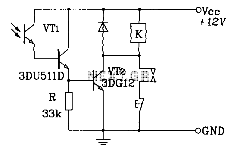
A Darlington phototransistor serves as the primary component for the photoelectric function within a self-locking control relay circuit. The circuit utilizes a Darlington phototransistor, which is known for its high current gain and sensitivity to light. This device is configured...

This project entitled Remote Control Through Internet allows us to monitor, control and automate our home from remote locations. In existing system home automation and security are separate systems working independently. Also in existing system if any one of...
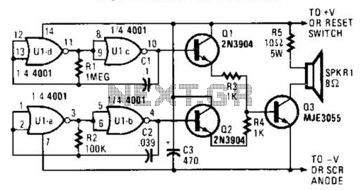
An external horn-type speaker is optimal for this circuit. However, such devices demand significant power, so this sounder should only be employed in alarm circuits utilizing at least a 6-A SCR as the sounder driver. The circuit incorporates a...

The circuit is constructed using two 555 timer integrated circuits (ICs), designated as U1 and U2. U1 is configured as a variable duty cycle oscillator with a fixed time period of approximately 0.1 seconds. The duty cycle can be...
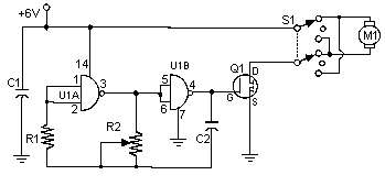
Often, people attempt to control DC motors with a variable resistor or variable resistor connected to a transistor. While the latter approach works well, it generates heat and hence wastes power. This simple pulse width modulation DC motor control...
This project involved the design of an audio amplifier capable of delivering substantial output power with minimal component count while maintaining high quality. The power amplifier section utilizes three transistors along with a few resistors and capacitors in a...