
28 LED Clock Timer
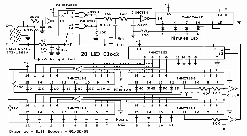
The 28 LED Clock Timer Circuit is designed to provide a visual representation of time through the use of individual light-emitting diodes (LEDs). The circuit employs a microcontroller that manages the timing functions and controls the illumination of the LEDs. The arrangement of 12 LEDs in a circular pattern represents the hours, while another set of 12 LEDs indicates the minutes, allowing for a clear and intuitive display of time.
To implement this circuit, a microcontroller such as an ATmega or PIC can be utilized for its programmable capabilities. The microcontroller is connected to a real-time clock (RTC) module, which keeps accurate time even when the main power is off. The RTC communicates with the microcontroller via I2C or SPI protocols, providing the current hour and minute information.
The LEDs should be connected to the microcontroller through current-limiting resistors to prevent damage due to excess current. Each LED representing an hour can be activated in sequence, while the minute LEDs can be activated in a similar manner, allowing for a visual countdown or timing function.
Power supply considerations are crucial for this circuit. A regulated power supply, typically 5V, is recommended to ensure stable operation of the microcontroller and LEDs. Additionally, capacitors may be added to the power lines to filter out noise and stabilize the voltage.
For user interaction, buttons can be integrated into the circuit to allow users to set the current time or switch between different timer modes. The circuit can also include a buzzer for audible alerts when the timer reaches a predetermined limit.
In summary, the 28 LED Clock Timer Circuit is a visually engaging timekeeping device that utilizes a microcontroller and a combination of LEDs to represent hours and minutes. Its design can be adapted for various applications, including timers, clocks, and educational tools for teaching time management.28 LED Clock Timer Circuit This is a programmable clock timer circuit that uses individual LEDs to indicate hours and minutes. 12 LEDs can be arranged in a circle to represent the 12 hours of a clock face and an additional 12 LE..
🔗 External reference
Related Circuits
The finger, positioned within a light screen, is situated between a high-intensity LED emitter and a photocell. It generates a heartbeat signal that, when appropriately amplified, serves as the input for a PIC16F84 microcontroller. The microcontroller drives three common...
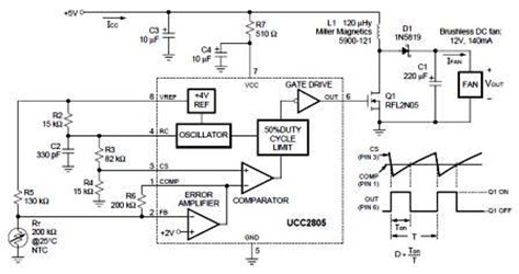
A temperature-controlled pulse-width-modulator (PWM) boost converter circuit diagram is illustrated in the following figure. This boost converter is designed to operate a 12V fan using a 5V supply while maintaining temperature control. The temperature-controlled PWM boost converter circuit operates by...
This is a very simple 555 timer circuit that serves as a straightforward theft deterrent, which may be just as effective. The idea is to have a flashing red LED indicate that your car is protected. This device can...
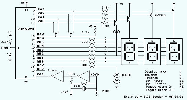
This clock timer uses a PIC16F628 microcontroller to display 3 and 1/2 digit time and control an external load. The clock includes a calendar with leap year and optional daylight savings adjustments. The timer output can be set from...
This simple and inexpensive circuit is not limited to Christmas use. It consists of two resistors, a small-signal transistor such as a BC547, and a flashing LED. The circuit operates by utilizing a small-signal transistor, which acts as a switch...

This circuit features an adjustable output timer that can re-trigger at specified intervals. The output duration can range from a fraction of a second to over half an hour, with the ability to repeat at consistent intervals from seconds...
Warning: include(partials/cookie-banner.php): Failed to open stream: Permission denied in /var/www/html/nextgr/view-circuit.php on line 713
Warning: include(): Failed opening 'partials/cookie-banner.php' for inclusion (include_path='.:/usr/share/php') in /var/www/html/nextgr/view-circuit.php on line 713