
5V Power Supply For On-Train Radio Camera

The design of a radio camera system for a model railway requires careful consideration to ensure continuous transmission while the train is in motion, as well as a delay in the transmission after the train has come to a stop. This system can be implemented using a combination of a radio transmitter, a camera module, a microcontroller, and a power management circuit.
The camera module should be capable of capturing video or images and encoding them for transmission. Common choices for such modules include the Raspberry Pi Camera Module or a small CMOS camera, which can provide sufficient resolution for model railway applications. The camera should be interfaced with a microcontroller, such as an Arduino or a Raspberry Pi, which will handle the control logic and manage the data flow from the camera to the transmitter.
The radio transmitter can be a low-power RF module, such as those operating in the 2.4 GHz ISM band, which is suitable for video transmission. The transmitter should be connected to the microcontroller, allowing it to send the encoded video data wirelessly to a receiver located at a fixed position.
To achieve the desired functionality of continuous transmission during movement and a few minutes of transmission after stopping, the microcontroller should be programmed with specific logic. It will monitor the train's motion using a simple motion sensor or a speed sensor. When the train is in motion, the microcontroller will activate the camera and transmitter, ensuring that video is constantly being sent. Upon detecting that the train has stopped, the microcontroller should initiate a timer that continues the transmission for a predetermined duration, allowing for the capture of any final moments before the system powers down.
Power management is crucial for this system, especially considering the limited space on a model train. A compact battery pack, possibly using lithium-polymer (LiPo) batteries, can provide the necessary power. A voltage regulator may be needed to ensure that both the camera and transmitter receive stable voltage levels. Additionally, implementing a low-power sleep mode for the microcontroller when the train is stationary can help conserve battery life.
Overall, this radio camera system will enhance the model railway experience, providing real-time video feedback and a unique perspective of the train's journey while ensuring efficient power usage and effective data transmission.A radio camera on a model railway should transmit constantly while the train is moving and continue transmitting for a few minutes after the train stops 🔗 External reference
Related Circuits
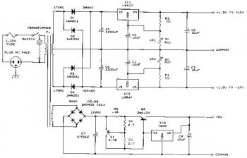
This bench power supply features three solid-state DC power supplies. The first supply provides an output of 1.5 to 15 volts at 1 ampere. The second supply offers a range of -1.5 to -15 volts at 1 ampere. The...
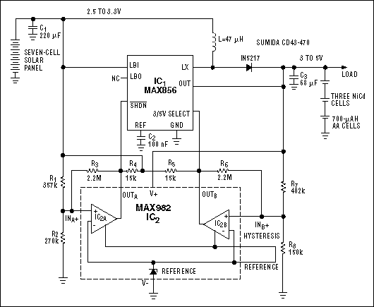
This circuit is designed to charge NiCd or NiMH batteries using solar cells. It maximizes power extraction from a solar array to charge a battery stack. The circuit utilizes the MAX856 boost converter and the MAX982 dual comparator with...
The following circuit illustrates a Radio Remote Control Circuit Diagram. This circuit is based on the UM91214B integrated circuit (IC) and features the use of DTMF (dual-tone multi-frequency) signaling. The Radio Remote Control Circuit utilizing the UM91214B IC is designed...
When the input voltage is between 198-242V, the average load current should be maintained at 0.5-1A, and the output voltage must remain at 15V with an error margin of less than 5%. The design and measurement of the stabilized...
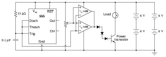
This circuit utilizes a 555 timer to generate a sawtooth voltage waveform across a capacitor, which is then compared to a steady voltage provided by a potentiometer using an operational amplifier (op-amp) configured as a comparator. The comparison of...
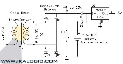
This circuit supplies electric power from a backup battery when AC power is interrupted, ensuring a stable 5V power supply for sensitive devices such as microcontrollers and logic circuits. The capacitor C1 should have a capacitance greater than 220...